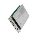
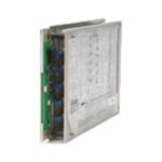
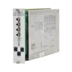
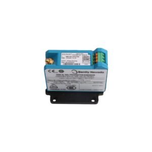
The Bently Nevada 3300/55-03-04-14-14-00-00-07-00, also cataloged as the 3300/55 Dual Thrust Position Monitor, operates as a dedicated hardware component for continuous dual-channel axial shaft position tracking within 3300 Monitoring System platforms.
Suffix Breakdown & Model Matrix
03: Full-scale range configuration option
04: Transducer input selection option
14: Channel A alarm relay hardware configuration option
14: Channel B alarm relay hardware configuration option
00: Recorder output option configuration
00: Dual-channel alarm reset option
07: Special internal firmware modification option
00: Factory standard agency approval option
Hardware Specifications
Parameter
Specification
Model
3300/55-03-04-14-14-00-00-07-00
Brand
Bently Nevada
Origin
USA
Weight
1.05 kg
Dimensions
83 mm x 244 mm x 120 mm
Operating Temp
0 deg C to +65 deg C
Power Consumption
7.8 W nominal
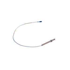
Input Signal
Dual independent proximity transducer inputs
Recorder Output
User-programmable +4 to +20 mA or 0 to -10 VDC proportional loops
Relay Module
Dual independent internal relay blocks for alert and danger thresholds
Machinery Monitoring and TSI Characteristics
The module maintains precise eddy-current probe scaling to convert analog voltage fluctuations directly into micrometer or mil axial displacement metrics. During continuous machine operation, the input circuitry executes automatic gap voltage validation (-10 VDC targets) to verify that the target shaft face remains within the linear measurement range of the proximity probe. Consequently, this tracking isolates actual rotor axial displacement from voltage drift. To avoid signal contamination within multi-probe environments, integrated cross-talk suppression circuitry isolates the input lines, which preserves data fidelity for assessing real-time rotor dynamics and bearing wear.
Frequently Asked Questions
Q: Why is gap voltage validation critical specifically for thrust position monitoring?
A: Thrust monitoring measures minute axial displacement toward or away from the sensor. Constant validation at the -10 VDC nominal center point ensures the probe operates within its linear calibration window, preventing false trips caused by an off-center physical setup.
Q: How does the monitor handle an absolute sensor failure versus an actual machine surge event?
A: The monitor utilizes independent Not OK diagnostic loops. If a probe signal drops out or shorts, the Not OK logic clamps the channel output and inhibits the Danger relays within 15 milliseconds, differentiating a hardware failure from actual mechanical thrust wear.
Field Installation Guidelines
Isolate all power lines to the main 3300 chassis before sliding the monitor card into its designated backplane slot to prevent card edge damage.
Route the proximity transducer extension cables through grounded metal conduit, keeping them separate from power cables to avoid high-voltage noise induction.
Terminate all shield drain wires directly at the designated chassis ground bar located on the rear terminal block assembly to optimize signal shielding.
Additional information
Weight
1.05 kg
Dimensions
260 × 210 × 140 mm
0.0
Average Rating
Rated
(0 Reviews)
Rated
0%
Rated
0%
Rated
0%
Rated
0%
Rated
0%
Be the first to review “Bently Nevada 3300/55-03-04-14-14-00-00-07-00 Dual Thrust Position Monitor” Cancel reply


0.0 Average Rating Rated (0 Reviews)