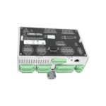
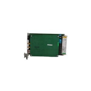
Configured for continuous turbine supervisory instrumentation monitoring in machinery protection chassis, the Bently Nevada 3300/01 (3300/01 System Monitor) provides direct physical/electrical execution. Specifically, the system manages rack power distribution, interfaces external communications, and governs the common alarm relay circuitry, thereby stabilizing the operational environment for adjacent plug-in monitoring modules.
Hardware Specifications
Parameter
Specification
Model
3300/01
Brand
Bently Nevada
Origin
USA
Weight
0.9 kg
Dimensions
241 mm x 24.4 mm x 163 mm
Operating Temp
0 to +65 deg C
Power Consumption
4.5 W typical
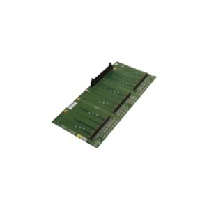
Slot Requirements
Occupies the far-left position (Slot 1) in a 3300 rack
Front Panel Display
LED status indicators (SUPPLIES OK, TRIP MULTIPLY)
Key Function
System rack power control, reset command routing, and OK relay management
Machinery Monitoring and Transducer Interface Dynamics
The processing hardware executes real-time eddy-current probe scaling to accurately translate physical displacement into precise electrical potentials. Consequently, gap voltage validation enforces an operational baseline of -10 VDC for standard proximity sensors, which ensures that the transducer maintains its linear range during high-frequency rotor dynamics observations. Furthermore, dynamic signal isolation circuitry constrains cross-talk suppression to under -60 dB across adjacent measurement paths, thereby preventing electrical resonance interference from corrupting critical vibration calculations.
Frequently Asked Questions
Q: What specific hardware function does the “SUPPLIES OK” front-panel indicator represent?
A: The green LED directly verifies that both the internal +5 VDC logic supply and the external -24 VDC transducer power rails remain within normal operating tolerances. Consequently, any voltage drop below preset diagnostic limits immediately de-energizes the system OK relay.
Q: Can an engineer hot-swap the 3300/01 module while the remaining rack monitors actively protect machinery?
A: Removing the system monitor disrupts the shared power bus lines and common relay logic paths across the backplane. Therefore, engineers must power down the rack assembly prior to pulling the module to prevent false trip execution on active channels.
Field Installation Guidelines
Rack Insertion and Faceplate Grounding: Slide the module into the designated left-most slot until the rear edge connectors seat fully into the backplane mating block. Next, tighten the upper and lower captive thumbscrews to ground the front aluminum faceplate directly to the main chassis frame.
Shield and Drain Wire Continuity: Terminate all external sensor shields at the rear backplane terminal strip using the shortest possible path. In addition, maintain strict physical isolation between the instrument ground bus and local high-current safety grounds, thereby eliminating stray ground loops.
Airflow and Clearance Demands: Maintain unhindered vertical convection boundaries around the rack frame enclosure. Specifically, reserve at least 80 mm of clearance above and below the chassis layout to prevent excessive thermal stagnation on the interior components.
Additional information
Weight
0.90 kg
Dimensions
50 × 70 × 90 mm
0.0
Average Rating
Rated
(0 Reviews)
Rated
0%
Rated
0%
Rated
0%
Rated
0%
Rated
0%
Be the first to review “Bently Nevada 3300/01 System Monitor” Cancel reply


0.0 Average Rating Rated (0 Reviews)