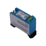
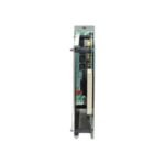
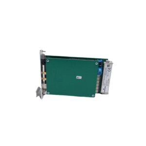
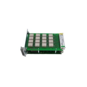
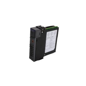
The Bently Nevada 3300/15-03-01-01-00-00-00, also cataloged as the 3300/15 Dual Vibration Monitor, operates as a dedicated hardware component for continuous radial vibration monitoring within machinery protection systems. Specifically, the system receives raw high-frequency waveforms from two independent proximity probe transducers, subsequently translating these inputs into peak-to-peak displacement values and proportional 4-20 mA recorder loops.
Suffix Breakdown & Model Matrix
The complete alphanumeric product code structures the specific hardware selection factory-installed into this vibration tracking block assembly:
Option Field
Ordered Suffix Code
Functional Component Definition
Transducer Type
03
3300 or 7200 5mm / 8mm Proximity Transducer Systems
Agency Approval
01
CSA / NRTL / C Class I, Division 2 groups A, B, C, D
Intrinsically Safe
01
Internal zener barriers configured for hazardous zone protection
Output Option
00
Standard 4-20 mA DC analog loop outputs
Relay Option
00
No individual channel relays installed (utilizes rack common relays)
Trip Multiply
00
Factory standard 2X or 3X trip multiplication function enabled
Modbus Option
00
No direct internal Modbus digital communications card
Hardware Specifications
Parameter
Specification
Model
3300/15-03-01-01-00-00-00
Brand
Bently Nevada
Origin
USA
Weight
1.1 kg
Dimensions
241 mm x 48.8 mm x 163 mm
Operating Temp
0 to +65 deg C
Power Consumption
7.2 W maximum
Signal Inputs
2 independent proximity probe channels
Analog Outputs
2 proportional 4-20 mA current loops
Accuracy
Within 0.5% of full-scale voltage span
Frequency Response
4 Hz to 10 000 Hz (-3 dB limits)
Machinery Monitoring and Transducer Interface Dynamics
The processing hardware executes real-time eddy-current probe scaling to accurately translate physical displacement into precise electrical potentials. Consequently, gap voltage validation enforces an operational baseline of -10 VDC for standard proximity sensors, which ensures that the transducer maintains its linear range during high-frequency rotor dynamics observations. Furthermore, dynamic signal isolation circuitry constrains cross-talk suppression to under -60 dB across adjacent measurement paths, thereby preventing electrical resonance interference from corrupting critical vibration calculations.
Frequently Asked Questions
Q: How do internal zener barriers affect proximity sensor selection for Suffix 01 configuration?
A: The internal zener barriers limit maximum fault energy routed to the field, yet they introduce precise inline resistance values. Therefore, technicians must calibrate the connected proximity sensor driver loops using the exact barrier impedance match to preserve linear scale factor verification.
Q: What physical system failure occurs if an engineer attempts to pull the 3300/15 module under active power?
A: Removing the active monitor forces an immediate open-circuit state across the rack-wide OK relay bus line. As a result, the master system executes a false system bypass sequence or trips shared safety interlocks unless engineers engage the rack hardware bypass switches prior to maintenance.
Field Installation Guidelines
Field Wiring and Shield Terminal Isolation: Wire the transducer coaxial extension cables directly to the rear backplane terminal block assignment. Next, isolate the outer shield braid completely at the probe junction box, and then terminate the drain wire only at the designated rack ground bar to block induced magnetic field noise loops.
Signal Cable Conduit Segregation: Run all dynamic low-voltage sensor lines inside dedicated rigid steel conduits. Specifically, isolate these signal channels from neighboring high-amperage variable speed drive outputs or motor control grid wiring.
Module Retaining Screw Engagement: Slide the monitor firmly along the guide tracks until the edge connectors lock flush with the backplane pin field. Afterwards, torque the upper and lower captive panel fasteners to establish full chassis ground bonding across the aluminum enclosure front plate.
Additional information
Weight
1.10 kg
Dimensions
70 × 70 × 60 mm
0.0
Average Rating
Rated
(0 Reviews)
Rated
0%
Rated
0%
Rated
0%
Rated
0%
Rated
0%
Be the first to review “Bently Nevada 3300/15 Dual Vibration Monitor” Cancel reply


0.0 Average Rating Rated (0 Reviews)