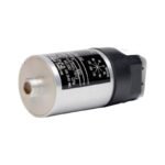
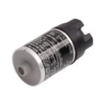
Purchase the Bently Nevada 9200-06-05-05-00 Seismoprobe Velocity Transducer. Brand New, Original Stock, and ready for Global Shipping with full factory warranties.
Configured for absolute casing vibration measurement in industrial machinery monitoring systems, the Bently Nevada 9200-06-05-05-00 (9200 Velocity Transducer) provides direct physical/electrical execution. The instrument utilizes an internal moving-coil design to generate a voltage signal directly proportional to the absolute velocity of the monitored structure or bearing housing. This specific configuration operates across a defined orientation window without drawing external excitation power from connected processing monitors.
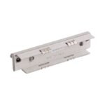
05: Connector/Cable Option (Terminal block top mount design, supplied with no integral cable assembly)
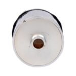
05: Mounting Base Option (No standalone base configuration, utilizes an integrated $1/2\text{-in } 20\text{ UNF-3A}$ threaded stud)
00: Agency Approval Option (Standard uncertified hardware variant, no hazardous area approvals required)
Hardware Specifications
Parameter
Specification
Model
9200-06-05-05-00
Brand
Bently Nevada
Origin
USA
Weight
300 grams (10.5 ounces) typical
Dimensions
41 mm diameter x 102 mm height typical
Operating Temp
-29 deg C to +121 deg C
Power Consumption
0.0 W (Self-generating passive moving-coil architecture)
Scale Factor Sensitivity
20 mV/mm/s (500 mV/in/s) $\pm 5\%$ at calibration angle
Frequency Response
10 Hz to 1000 Hz (600 cpm to 60,000 cpm) $\pm 3\text{ dB}$ typical
Coil Resistance
1.25 kOhm $\pm 5\%$
Transverse Sensitivity
Less than or equal to $10\%$ of axial sensitivity
Machinery Monitoring and TSI Characteristics
The 9200-06-05-05-00 serves a dedicated function within structural Turbomachinery Instrumentation (TSI) layouts, recording low-to-medium frequency casing velocity loops where proximity sensors cannot capture high-mass bearing housing deflections. The moving-coil system relies on precise eddy-current probe scaling mechanics inside concurrent proximity systems to correlate shaft-to-casing relative dynamics. Because the sensor operates without power, internal signal isolation parameters preserve cross-talk suppression paths within shared machinery conduits. During steady-state and transient machine cycles, the sensor monitors rotor dynamics data down to $10\text{ Hz}$ while remaining highly resilient against high-frequency impulse spikes that typically cause solid-state accelerometer saturation.
Frequently Asked Questions
Q: Does the 9200-06-05-05-00 require an active -24 VDC proximity loop power supply from the 3500 monitor rack?
A: No. The moving-coil assembly operates entirely passively, generating its own millivolt signal via physical magnetic induction. Connecting an external power loop directly to terminal connections A and B will damage the internal coil winding.
Q: Can this specific transducer variation be mounted horizontally on a machine casing?
A: Yes. The “06” prefix designation permits a mounting window of $0 \pm 100$ deg relative to the horizontal or vertical calibration axis. This operational range gives field installation teams flexibility to angle the sensor assembly without provoking internal spring suspension bottoming.
Field Installation Guidelines
Mechanical Torque Interfacing: Clean the machine casing surface until a flat, smooth bare-metal seating interface is exposed. Hand-thread the integral $1/2\text{-in } 20\text{ UNF-3A}$ mounting stud directly into the perpendicular tapped housing hole, then torque the transducer body to a fixed value of 5.6 N-m (50 in-lb).
Terminal Wiring Enclosure: Connect field wiring pairs to the top terminal block assembly using clean ring or spade lugs. Ensure that the terminal enclosure cover remains properly sealed and tracking threads are protected to shield the exposed bare connections from oil spray and ambient atmospheric moisture.
Shield Continuity Management: Terminate the external twisted-pair signal shield only at the 3500 or 3300 monitor rack terminal strip. Cut and isolate the shield at the sensor end to maintain a single-point grounding configuration, preventing structural current noise from leaking onto the 20 mV/mm/s analog signal path.
Additional information
Weight
0.8 kg
Dimensions
32 × 20 × 12 mm
0.0
Average Rating
Rated
(0 Reviews)
Rated
0%
Rated
0%
Rated
0%
Rated
0%
Rated
0%
Be the first to review “Bently Nevada 9200-06-05-05-00 Seismoprobe Velocity Transducer” Cancel reply


0.0 Average Rating Rated (0 Reviews)