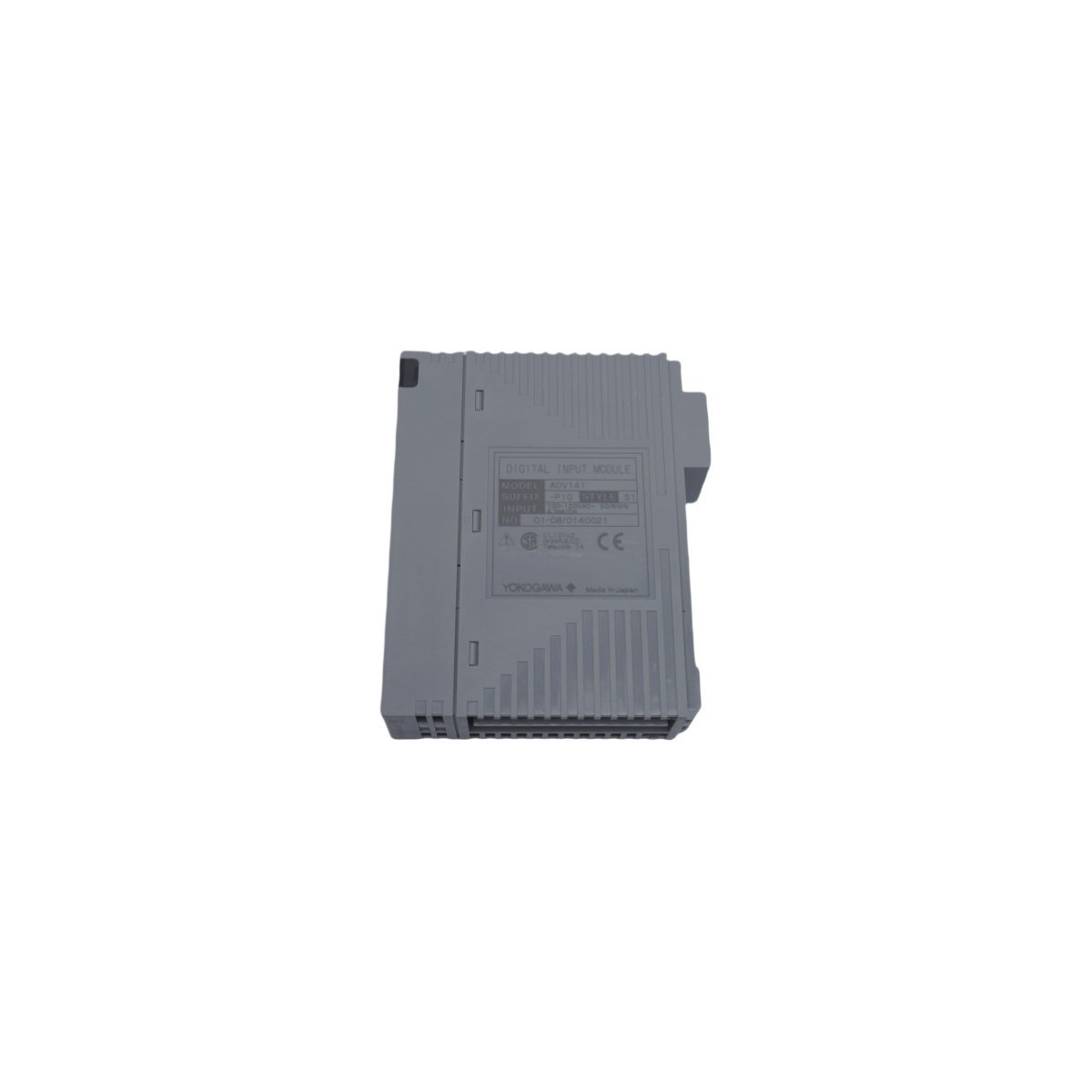
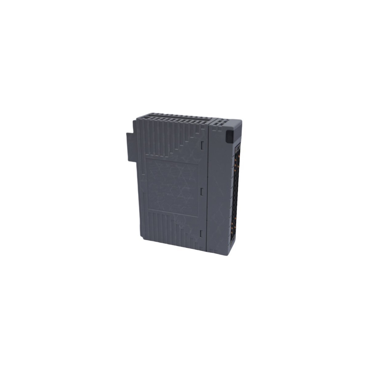
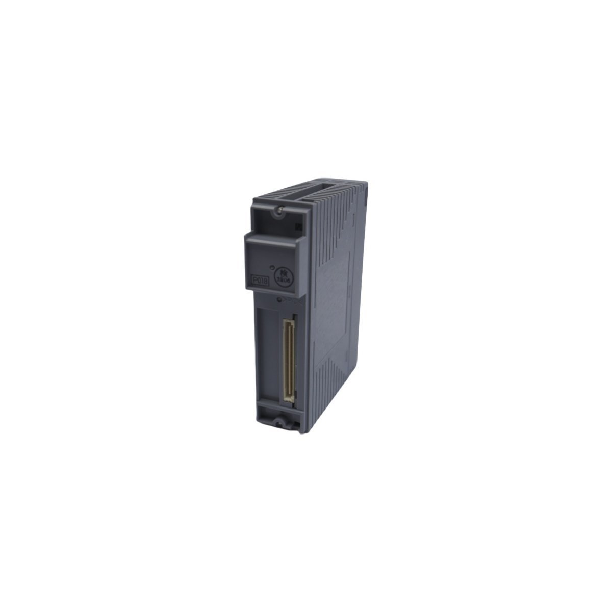
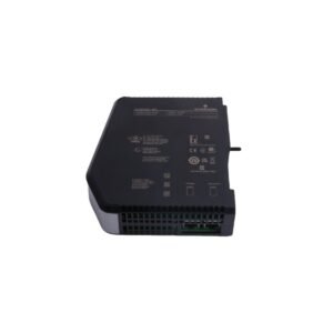
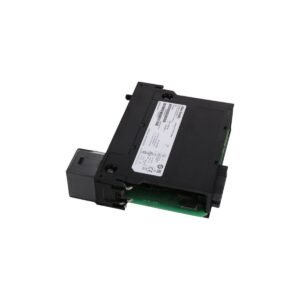
Configured for high-density signal acquisition in CENTUM VP DCS platforms, the Yokogawa ADV141-P10 S1 (ADV141-P10 Digital Input Module) provides direct physical electrical state sensing and logic conversion for process control loops.
Hardware Specifications
Parameter
Specification
Model
ADV141-P10 S1
Brand
Yokogawa
Origin
Japan
Weight
0.28 kg
Dimensions
3.2 x 10.7 x 13 cm
Operating Temp
Standard Industrial Grade
Power Consumption
System-bus compliant
Module Type
Digital Input
System Platform
CENTUM VP
Process Control and DCS Connectivity
The ADV141-P10 S1 incorporates channel-to-channel isolation to mitigate noise interference in complex field wiring environments. In accordance with DCS signal standards, this module supports high-speed scan intervals necessary for transient event detection within the control network. Precise cold junction compensation (CJC) logic is integrated into the backplane processing architecture to ensure signal integrity across all digital transition states, facilitating accurate status monitoring within the CENTUM VP environment.
Frequently Asked Questions (FAQ)
Q: What is the primary function of the S1 suffix in this module designation?
A: The S1 suffix denotes the specific hardware revision level and environmental coating specification mandated by the manufacturer to ensure compatibility with standard CENTUM VP backplane interfaces.
Q: Is this module capable of hot-swapping during system operation?
A: The ADV141-P10 S1 is designed for operation within the standard CENTUM VP I/O nest; however, users must verify the specific cabinet power-down procedures and node-level interlock status before executing physical module replacement to prevent backplane bus disturbance.
Q: How is the module isolated from field-side voltage spikes?
A: The module utilizes galvanic isolation between the field input terminals and the internal system bus, protecting the DCS logic components from high-voltage transient surges originating from the connected field devices.
Field Installation Guidelines
Prior to installation, ensure the DIN-rail or chassis mounting surface is clean and free of conductive debris to maintain proper grounding contact.
Subsequently, verify that the input voltage levels from field devices correspond to the module input voltage ratings before establishing the terminal block connection.
Furthermore, route field input signal cables through dedicated conduits, maintaining a minimum physical separation of 300 mm from high-voltage power lines to reduce EMI/RFI coupling.
In addition, utilize shielded twisted-pair cabling for all input signals, ensuring the shield is terminated to the designated chassis ground point at the cabinet entry level.
Finally, tighten terminal block screws to the manufacturer-specified torque value (typically 0.5 Nm) to prevent connection loosening under vibration.
Additional information
Weight
0.28 kg
Country of Origin
Japan
Dimension
3.2 x 10.7 x 13 cm
0.0
Average Rating
Rated
(0 Reviews)
Rated
0%
Rated
0%
Rated
0%
Rated
0%
Rated
0%
Be the first to review “Yokogawa ADV141-P10 S1 Digital Input Module” Cancel reply







0.0 Average Rating Rated (0 Reviews)