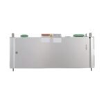
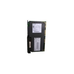
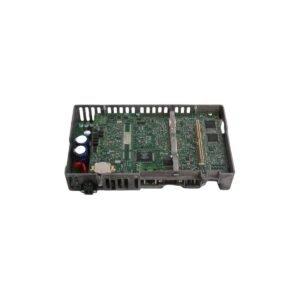
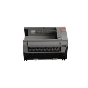
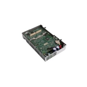
The Bently Nevada 125800-01 is a 3500/25 Keyphasor I/O Module with Internal Terminations. We supply Brand New, Original Stock items with complete Global Shipping coverage.
Configured for phase reference extraction and rotational timing distribution in the 3500 Monitoring System, the Bently Nevada 125800-01, also cataloged as the 3500/25 Keyphasor I/O Module, provides direct physical/electrical execution. This half-height interface component features internal terminations to accept physical raw sensor links from field-mounted proximity probes or magnetic pickups. The device converts analog voltage pulses into square-wave timing markers, feeding them immediately across the internal rack backplane to support synchronous vibration data sampling and multi-channel orbit analysis.
Hardware Specifications
Parameter
Specification
Model
3500/25 125800-01
Brand
Bently Nevada
Origin
USA
Weight
0.38 kg
Dimensions
25.0 mm x 112.0 mm x 242.0 mm
Operating Temp
-30 to +65 deg C
Power Consumption
3.2 W typical
Bandwidth
0 to 10 kHz
Accuracy
+/- 0.5 degrees
Input Signal Range
+0.8 V to -21.0 V (Non-Isolated configuration)
Output Drive Capacity
-24 VDC, 40 mA maximum per channel
Termination Style
Internal Termination (Euro-Style terminal blocks)
Mechanical Monitoring & TSI Characterization
The 3500/25 125800-01 applies continuous eddy-current probe scaling to translate fluctuating target voltages into definitive edge triggers. Consequently, the card executes real-time gap voltage validation (-10 VDC targets) to verify baseline sensor distance and signal linearity before approving speed metrics. When dense gear profiles or proximity notches induce physical sensor field overlap, the integrated cross-talk suppression logic isolates individual pulse transitions, sustaining uninterrupted tracking of rotor dynamics during high-vibration events.
Frequently Asked Questions
Q: What is the physical limitation of passive magnetic pickups when wired into the 125800-01 termination block?
A: Passive magnetic pickups do not receive external transducer power. Therefore, the monitored shaft must achieve a minimum rotational velocity greater than 200 rpm to generate the 500 mV peak-to-peak signal threshold needed to actuate the internal timing logic.
Q: Can the internal termination blocks on this module be swapped while the rack is powered?
A: No. Technicians must de-energize the field wiring or the entire slot block before manipulating the Euro-Style screw connectors to prevent accidental short circuits across the -24 VDC transducer power lines.
Field Installation Guidelines
Shield Grounding Protocol: Land the braided drain wire of all field extension cables directly onto the rack chassis instrumentation earth strip. Float the shield completely at the sensor housing end to preserve a single-point grounding configuration that mitigates electromagnetic noise injection.
Module Retaining Assembly: Insert the I/O card into the rear slot of the 3500 rack alignment track. Drive the connector pins forward until they seat securely against the main module interface, then tighten the captive panel screws to an exact torque specification of 0.56 N-m.
Field Wiring Constraints: Strip insulation from the field wires back precisely 7 mm before insertion into the Euro-Style clamping terminals. Ensure no stray wire strands escape the terminal boundary to rule out adjacent channel shorting risks inside the enclosure.
Additional information
Weight
0.38 kg
Dimensions
70 × 210 × 210 mm
0.0
Average Rating
Rated
(0 Reviews)
Rated
0%
Rated
0%
Rated
0%
Rated
0%
Rated
0%
Be the first to review “Bently Nevada 3500/25 125800-01 Keyphasor I/O Module” Cancel reply


0.0 Average Rating Rated (0 Reviews)