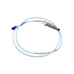
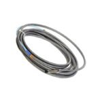
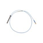
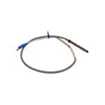
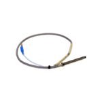
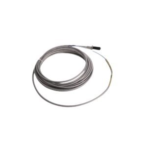
The Bently Nevada 330102-00-12-10-02-05, also cataloged as the 330102 Proximity Probe, operates as a dedicated hardware component for non-contact shaft displacement and vibration measurement within Bently Nevada 3500 Machinery Protection System platforms.
Hardware Specifications
Parameter
Specification
Model
330102-00-12-10-02-05
Brand
Bently Nevada
Origin
USA
Weight
0.32 kg
Dimensions
3/8-24 UNF thread, 1.2 in unthreaded length, 1.0 m total length
Operating Temp
-51 to +177 deg C
Power Consumption
Passive element (driven by external Proximitor Sensor)
Probe Diameter
8 mm
Thread Type
Reverse mount, 3/8-24 UNF
Total Length
1.0 m (3.3 ft)
Linear Range
2.0 mm (80 mils)
Scale Factor
7.87 V/mm (200 mV/mil)
Eddy-Current Probe Scaling and Gap Voltage Validation
The probe tip continuously generates a high-frequency eddy-current field to detect the target position. Consequently, the change in distance between the probe tip and the target material modulates the RF field impedance. To establish accurate baseline metrics, the engineer must perform a formal gap voltage validation. Specifically, the technician adjusts the mechanical positioning until the system registers a -10 VDC target, which marks the exact center of the linear operational range against standard AISI 4140 steel. Furthermore, monitoring the rotor dynamics ensures that the probe maintains proper clearance without risking physical contact during high-speed rotation. Finally, proper physical separation between the transducer leads and neighboring high-voltage lines achieves optimal cross-talk suppression.
Frequently Asked Questions
Q: Why must the engineer establish a -10 VDC gap voltage during initial setup?
A: This voltage confirms that the technician has mechanically positioned the probe tip at the midpoint of its 80 mil linear range. As a result, the system maintains symmetric measurement capability for both positive and negative shaft displacements.
Q: How does the total cable length influence the calibration of the loop?
A: The internal circuitry relies on a specific loop impedance; therefore, changing the cable length directly alters the system calibration. The technician must connect this 1.0 m probe to an extension cable and Proximitor Sensor that match either a 5.0 m or 9.0 m total system configuration. Otherwise, the mismatched impedance shifts the scale factor away from the standard 200 mV/mil specification.
Field Installation Guidelines
Thread the probe into the standard 3/8-24 UNF tapped hole. Ensure at least 5 full thread engagements to secure the reverse-mount assembly properly.
Inspect the target surface before completing the installation. The engineer must remove mechanical scratches, pits, and localized magnetic fields, because these imperfections generate electrical runout errors.
Clean all coaxial connectors with a zero-residue electronic cleaner. Immediately following the cleaning, apply self-fusing silicone tape over the mated connection to seal out environmental moisture.
Route the sensor cable through dedicated, grounded metal conduit. This shielding protects the signal from electromagnetic interference and prevents mechanical abrasion along the cable run.
Additional information
Weight
0.32 kg
Dimensions
55 × 60 × 70 mm
0.0
Average Rating
Rated
(0 Reviews)
Rated
0%
Rated
0%
Rated
0%
Rated
0%
Rated
0%
Be the first to review “Bently Nevada 330102-00-12-10-02-05 3300 XL 8 mm Proximity Probe” Cancel reply


0.0 Average Rating Rated (0 Reviews)