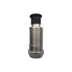
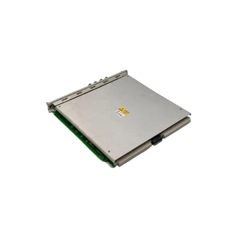
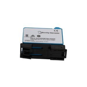
The Bently Nevada 134M0389-04, also cataloged as the 134M0389 Wireless Triaxial Vibration Sensor, operates as a dedicated hardware component for triaxial acceleration and surface temperature data acquisition within ISA100.11a wireless machinery monitoring networks. It collects high-resolution dynamic vibration profiles directly from rotating machinery bearings and structural housings, converting mechanical motion into digitized wireless payloads for condition monitoring host systems without requiring field signal cables.
Hardware Specifications
Parameter
Specification
Model
134M0389-04
Brand
Bently Nevada
Product Type
Wireless Triaxial Vibration Sensor
Origin
USA
Weight
2.1 kg
Dimensions
88 mm x 45 mm x 45 mm
Operating Temp
-40 deg C to +85 deg C
Power Consumption
Internal 3.6 V Lithium Thionyl Chloride Battery Pack
Wireless Communication Protocol
ISA100.11a / IEEE 802.15.4
Sensing Axes
Triaxial (X, Y, Z axes)
Acceleration Range
+/- 80 g peak
Frequency Response
2 Hz to 10000 Hz (+/- 3 dB)
Enclosure Rating
IP67 / NEMA 4X
Machinery Dynamics and Signal Conditioning Attributes
The sensing hardware implements dedicated multi-axis piezoelectric accelerometer elements aligned along orthogonal spatial vectors to capture multi-plane rotor dynamics and structural resonance frequencies. Internal digital signal conditioning applies anti-aliasing filtering and dynamic range scaling prior to wireless packetizing. While continuous proximity transducer channels require eddy-current probe scaling and physical gap voltage validation against -10 VDC targets for journal bearing displacement, the 134M0389-04 sensor architecture relies on internal high-frequency sampling routines designed to eliminate high-frequency cross-talk suppression issues across triaxial axes during simultaneous spectral sampling.
Frequently Asked Questions
Q: What physical mounting interface is required to preserve high-frequency vibration transmission up to 10000 Hz?
A: High-frequency signal fidelity requires a direct stud mount on a flat, spot-faced machine surface prepared to a finish better than 1.6 um Ra. Using magnetic bases or adhesives introduces mechanical attenuation that reduces usable bandwidth above 2000 Hz.
Q: How does the wireless sensor payload handle battery consumption during high-rate data acquisition?
A: Power consumption is managed by configurable wake-up interval sleep cycles. Transmitting burst waveform data increases peak current draw; hence, interval timing parameters must be adjusted in the network gateway configuration to optimize battery life against spectral sampling resolution requirements.
Q: What procedure validates the mechanical grounding and internal shield isolation during field installation?
A: The sensor housing features an isolated base configuration to prevent ground loop currents from entering the internal signal conditioning circuit. Field checks require verifying infinite DC resistance (greater than 10 M ohm) between the sensor outer chassis and the mounting machine surface prior to final torque tightening.
Field Installation Guidelines
Machine Surface Preparation: Ensure the mounting location on the bearing housing is machined flat to a surface roughness of 1.6 um Ra or better. Remove paint, rust, and debris from the tapped mounting hole area.
Thread Engagement: Inspect the threaded mounting hole for correct engagement depth. Ensure a minimum of 5 full turns of thread engagement (or appropriate NPT/metric thread engagement limits) before applying torque.
Torque Application: Thread the sensor stud onto the prepared machine surface and apply a calibrated mounting torque of 4.5 N m (40 in lb). Do not over-torque, as this can distort the internal piezo-element stack.
Grounding and Isolation: Verify that the sensor body maintains physical isolation from stray ground potential differences. Confirm that shield continuity and signal grounding conform strictly to plant single-point grounding practices.
Network Commissioning: Power on the sensor via the internal battery isolation tab removal, then perform wireless join procedures through the ISA100.11a system manager interface to establish deterministic network routing.
Additional information
Weight
2.10 kg
Dimensions
65 × 78 × 84 mm
0.0
Average Rating
Rated
(0 Reviews)
Rated
0%
Rated
0%
Rated
0%
Rated
0%
Rated
0%
Be the first to review “Bently Nevada 134M0389-04 Ranger Pro Wireless Vibration Sensor” Cancel reply












0.0 Average Rating Rated (0 Reviews)