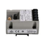
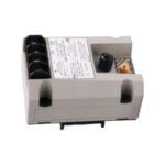
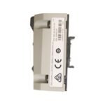
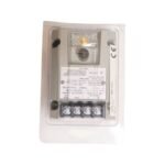
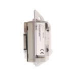
The Bently Nevada 991-25-70-01-CN serves as the primary 991 Thrust Transmitter utilized to execute axial displacement monitoring tasks across 3300 NSv Proximity Transducer System platforms.
Accepts 1 non-contacting 3300 NSv proximity probe and extension cable
Loop Current
4-20 mA DC over specified full-scale range
Supply Voltage
+12 to +35 VDC at transmitter terminal blocks
Maximum Load
1000 ohms loop resistance at 35 VDC
Rotor Dynamics and Gap Voltage Validation
The hardware interfaces directly with a 3300 NSv transducer system to track micro-level shaft axial variations and overall rotor dynamics. Commissioning procedures necessitate physical gap voltage validation, requiring a target setting of -10 VDC at the raw PROX OUT terminal to ensure the eddy-current probe operates within its optimized linear calibration spectrum. Furthermore, the specialized internal filtering design yields high-level cross-talk suppression, eliminating mutual inductance anomalies when multiple transmitters share a common DIN-rail ground plane.
Frequently Asked Questions
Q: How fast does the Not OK / Signal Defeat circuit respond to a field loop failure?
A: The transmitter internal circuit drives the analog current output down to less than 3.6 mA within 100 microseconds following a broken coaxial cable or probe fault condition.
Q: Is the raw PROX OUT coaxial output isolated from the primary 4-20 mA process loop?
A: No, the dynamic signal line shares a common ground path with the current loop. Therefore, engineers must utilize an isolated test adapter when collecting diagnostic data via mains-powered oscilloscopes.
Field Installation Guidelines
Mount the potted enclosure onto a standard 35 mm DIN-rail channel inside an environmentally secure housing. Maintain a minimum distance of 100 mm from three-phase industrial power lines to minimize electromagnetic noise pickup. Connect the 75-ohm FEP-insulated coaxial cable from the extension lead directly to the internal receiver module, ensuring the threads engage cleanly to eliminate interface impedance variations. Connect the overall current loop drain wire to the instrumentation chassis ground at the control room termination panel.
Additional information
Weight
0.8 kg
Dimensions
26 × 16 × 22 mm
0.0
Average Rating
Rated
(0 Reviews)
Rated
0%
Rated
0%
Rated
0%
Rated
0%
Rated
0%
Be the first to review “Bently Nevada 991-25-70-01-CN 991 Thrust Transmitter” Cancel reply


0.0 Average Rating Rated (0 Reviews)