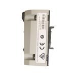
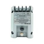
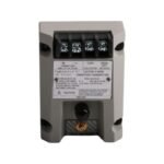
Configured for contactless eddy-current vibration and position monitoring in critical rotating machinery, the Bently Nevada 990-04-XX-01-00 (990 Transmitter) provides direct physical/electrical execution. This device processes high-frequency RF signals from a proximity probe tip to deliver a linearized 4-20 mA output proportional to radial vibration or axial position directly to PLC or DCS platforms.
Hardware Specifications
Parameter
Specification
Model
990-04-XX-01-00
Brand
Bently Nevada
Origin
USA
Weight
0.27 kg
Dimensions
81.3 mm x 61.2 mm x 43.2 mm
Operating Temp
-35 deg C to +85 deg C
Power Consumption
Max 0.8 W at 24 VDC
Input Range
Accepts standard 3300 XL 5mm/8mm proximity probe inputs
Output Signal
4-20 mA dc loop-powered proportional to configured full-scale range
Supply Voltage
12 VDC to 35 VDC at the transmitter terminals
Eddy-Current Probe Calibration and Gap Voltage Validation
The 990 Transmitter integrates the functions of a proximity sensor and a signal conditioner into a single enclosure. Field technicians must perform gap voltage validation during physical alignment using the BNC raw signal output port. Adjusting the proximity probe gap until the dynamic DC voltage reads -10 VDC targets the exact center of the linear calibration slope. This precise positioning is required to eliminate cross-talk suppression issues from nearby machinery housings and to ensure the proper monitoring of rotor dynamics under high-velocity transient speeds.
Frequently Asked Questions
Q: What does the “XX” variable represent in the 990-04-XX-01-00 configuration matrix?
A: The “XX” option code specifies the full-scale range and variable type. For example, an option of 50 indicates a 0-50 mils full-scale displacement range for axial position, while an option of 04 indicates a 0-4 mils peak-to-peak range for radial vibration.
Q: Does the 990-04-XX-01-00 require an external Proximitor to function?
A: No. The 990 Transmitter eliminates the need for an external Proximitor sensor by directly driving the probe and outputting a standard industrial 4-20 mA loop signal.
Field Installation Guidelines
DIN-Rail Mounting: Snap the 990 housing securely onto 35 mm DIN-rail backing tracks. Ensure the ground spring on the underside of the transmitter makes direct, paint-free mechanical contact with the metal rail.
BNC Terminal Validation: Connect a high-impedance digital voltmeter to the integrated BNC jack to measure the dynamic gap voltage. Adjust the probe depth until reaching the designated target voltage before tightening the mechanical jam nuts.
Terminal Wiring Constraints: Limit strip length to 7 mm for all field wiring connections. Tighten terminal block screws to a maximum torque specification of 0.5 N-m (4.5 in-lb) to prevent structural board deformation.
Shield Continuity: Loop current return lines must be shielded twisted-pair cables. Terminate the outer shield wire at the control system ground node only, keeping the transmitter chassis isolated from field loop returns.
Additional information
Weight
0.27 kg
Dimensions
81.3 × 61 × 43 mm
0.0
Average Rating
Rated
(0 Reviews)
Rated
0%
Rated
0%
Rated
0%
Rated
0%
Rated
0%
Be the first to review “Bently Nevada 990-04-XX-01-00 990 Transmitter System” Cancel reply


0.0 Average Rating Rated (0 Reviews)