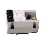
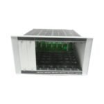
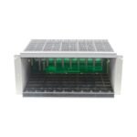
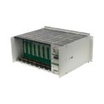
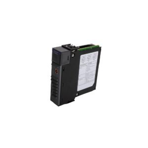
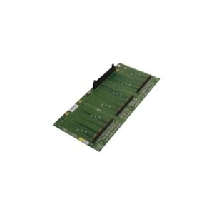
Configured for physical housing and backplane distribution in rotating machinery monitoring networks, the Bently Nevada 3300/05-25-01-01 (3300/05 Modular Rack Chassis) provides direct physical/electrical execution. This 12-position chassis forms the mechanical foundation of the legacy 3300 system, establishing a continuous structural frame and electrical backplane that routes power, common alarm buses, and raw transducer signals between installed monitoring modules.
Hardware Specifications
Parameter
Specification
Model
3300/05-25-01-01
Brand
Bently Nevada
Origin
United States
Weight
4.12 kg
Dimensions
482.6 mm x 132.6 mm x 266.7 mm
Operating Temp
-20 deg C to +65 deg C
Power Consumption
0.0 W (Passive structural backplane)
Position Capacity
12 individual hardware slots
Agency Approvals
CSA / NRTL / C (Class I, Div 2)
Mounting Type
Weatherproof enclosure / 19-inch rack frame
Eddy-Current Probe Scaling and Rotor Dynamics Calibration
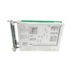
The 3300/05 rack chassis provides the backplane trace continuity required to process delicate proximity waveforms before they undergo monitor-stage analysis. Consequently, the backplane must maintain strict grounding integrity to preserve the exact eddy-current probe scaling configured during field setup. During initial module commissioning, field engineers perform gap voltage validation across all active channels to verify the steady-state -10 VDC target on each proximity probe loop. Because the 12-slot configuration packs up to 20 individual sensor loops in close physical proximity, the integrated backplane traces implement active cross-talk suppression. This layout prevents parasitic electromagnetic fields from bleeding into adjacent slots, thus isolating high-frequency harmonics and enabling uncorrupted monitoring of high-speed rotor dynamics.
Frequently Asked Questions
Q: Can this chassis support live hot-swap insertion of active 3300 monitor modules?
A: No. Unlike modern architectures, the legacy 3300/05 backplane does not feature sequenced power pins. Therefore, field technicians must completely remove power from the rack power supply module before inserting or extracting any monitor cards to avoid permanent circuit damage or accidental relay trips.
Q: How does the rack option “-25” affect the slot assignment layout?
A: The “-25” option specifies a 12-position chassis width. Consequently, slot 1 strictly accepts the system power supply, slot 2 accepts the system monitor card, and slots 3 through 12 accept individual machinery protection modules.
Field Installation Guidelines
Chassis Frame Grounding: Bond the rack frame directly to the main instrument ground bus using a minimum 4.0 mm squared (11 AWG) copper wire to ensure a low-impedance path.
Rear Service Clearance: Maintain a minimum clearance of 101.6 mm behind the rear terminal blocks to facilitate cable bend radii and to allow unhindered module removal.
Shield Continuity Management: Route all probe shield wires to the dedicated terminal strips located on the rear individual relay modules. Meanwhile, ensure the shield remains completely isolated and ungrounded at the machine junction box.
Ventilation Path Clearance: Install the chassis with at least 44.5 mm of open vertical space above and below the enclosure to prevent thermal heat traps from degrading internal components.
Additional information
Weight
0.6 kg
Dimensions
26 × 36 × 12 mm
0.0
Average Rating
Rated
(0 Reviews)
Rated
0%
Rated
0%
Rated
0%
Rated
0%
Rated
0%
Be the first to review “Bently Nevada 3300/05-25-01-01 3300 System Modular Rack” Cancel reply


0.0 Average Rating Rated (0 Reviews)