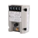
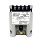
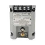
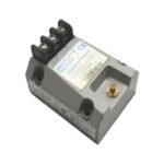
Bently Nevada 990-04-50-01-CN 990 vibration transmitter. Brand New, Original Stock, Global Shipping available for automated industrial machinery monitoring.
The Bently Nevada 990-04-50-01-CN, also cataloged as the 990 Vibration Transmitter, serves as the primary 990 Vibration Transmitter utilized to execute relative vibration monitoring across centrifugal air compressors, small pumps, motors, and fan platforms. This loop-powered, two-wire integrated hardware device directly accepts high-frequency signals from a 3300 NSv proximity probe assembly. Furthermore, the internal electronics condition this dynamic displacement data into a proportional linear 4-20 mA analog output, routing the machinery health metrics directly to the process control network without requiring intermediate monitoring racks.
Suffix Breakdown & Model Matrix
The specific alphanumeric configuration defines the factory calibration parameters, internal tuning values, and physical mounting mechanisms for this exact hardware assembly.
990: 990 Vibration Transmitter Series base designator featuring an integrated internal Proximitor sensor core.
04: Full-Scale Option (Calibrated for 0-4 mils peak-to-peak / 0-100 micrometres peak-to-peak linear range).
50: System Length Option (Tuned exclusively for a 5.0 metre total electrical combination of probe and extension cable).
01: Mounting Option (Equipped with standard 35 mm DIN rail clips).
CN: Agency Approval Option (Indicates full certification and compliance under China-specific industrial regulatory standards for hazardous areas).
Hardware Specifications
Parameter
Specification
Model
990-04-50-01-CN
Brand
Bently Nevada
Origin
United States
Weight
0.43 kg
Dimensions
100 mm x 74 mm x 53.3 mm
Operating Temp
-35 to +85 deg C
Power Consumption
12-35 VDC loop input voltage (23 mA maximum typical current limit)
Output Signal
4-20 mA DC linear vibration proportional loop
Loop Accuracy
Within +/-1.5% over the specified full-scale range
Linear Range
1.27 mm (50 mils) total displacement band
Dynamic Output
PROX OUT coaxial connector with 10 kohm output impedance
Frequency Response
5 Hz to 6,000 Hz (+0 dB, -3 dB attenuation points)
Eddy-Current Probe Scaling and Rotor Dynamics
To preserve accurate data streaming into predictive maintenance software, the integrated Proximitor circuit provides an internal incremental scale factor of 7.87 mV/micrometre (200 mV/mil). During initial field alignment, engineers execute gap voltage validation via the dedicated diagnostic BNC port, aiming for the linear midpoint. This adjustment requires adjusting the physical sensor distance until the dynamic gap voltage sits between the -10 VDC targets.
Proper calibration maintains stability across the 5 Hz to 6,000 Hz window, allowing the transmitter to capture subtle sub-synchronous or non-synchronous alterations in the machinery rotor dynamics profile. In addition, the internal potting engineering yields cross-talk suppression and isolates the signal paths from inductive ambient noise within shared conduits.
Frequently Asked Questions
Q: What action does the internal Not OK / Signal Defeat loop execute if the external 3300 NSv proximity probe fails?
A: The transmitter forces the current output down to less than 3.6 mA within 100 microseconds of a detected sensor circuit fault or loose cable connection. This function inhibits false high-vibration alarms within the machinery safety system.
Q: How do the non-interacting zero and span potentiometers modify the loop calibration?
A: The non-interacting zero and span potentiometers allow independent adjustment of the 4 mA baseline and 20 mA maximum points. Modifying the zero point does not shift the span setting, which significantly accelerates loop verification.
Field Installation Guidelines
Implement Terminal Block Torque Limits: Secure all electrical wire terminations on the screw terminal block using a maximum torque of 0.56 N m (5 in lb) to prevent structural damage to the physical wire-clamp cage.
Verify Enclosure Seal Integrity: Mount the unit inside an environmental junction box if the local environment exceeds 100% condensing humidity. Ensure that all conduit runs utilize a sealing drip loop to divert moisture away from the potted housing.
Enforce Shield Grounding Rules: Terminate the outer coaxial shield wire at a single point, specifically the COM terminal of the transmitter module. Do not ground the cable shield at both ends to eliminate industrial ground loop currents.
Check Target Face Dimensions: Position the probe tip over a flat target surface that provides a minimum target area diameter of 9.5 mm (0.375 inches) to prevent magnetic edge-effect errors from distorting the current loop output.
Additional information
Weight
0.55 kg
Dimensions
26 × 16 × 16 mm
0.0
Average Rating
Rated
(0 Reviews)
Rated
0%
Rated
0%
Rated
0%
Rated
0%
Rated
0%
Be the first to review “Bently Nevada 990-04-50-01-CN 990 Vibration Transmitter Module” Cancel reply


0.0 Average Rating Rated (0 Reviews)