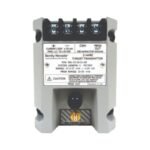
Bently Nevada 991-06-50-01-00 991 thrust position transmitter. Brand New, Original Stock, Global Shipping available for automated machine safety monitoring.
The Bently Nevada 991-06-50-01-00, also cataloged as the 991 Thrust Transmitter, serves as the primary 991 Thrust Transmitter utilized to execute continuous axial displacement tracking across centrifugal air compressor, small pump, and industrial fan platforms. This loop-powered, two-wire hardware component connects directly to an external 3300 NSv proximity probe assembly. The internal processing network conditions raw eddy-current gap fluctuations into a linear 4-20 mA analog output, streaming real-time shaft position metrics directly into process control systems for machinery safety logic verification.
Suffix Breakdown & Model Matrix
The unique alphanumeric code designators outline the factory-calibrated scale options, structural line tuning, and mechanical attachment mechanics engineered for this module.
991: 991 Series Two-Wire Thrust Position Transmitter base model with integrated internal Proximitor conditioning circuitry.
06: Full-Scale Range Option (Specifies a 1.2 mm total displacement band / typical full-scale calibration mapping of 0.6-0-0.6 mm or 25-0-25 mils).
50: System Length Option (Tuned exclusively for a 5.0 metre total electrical combination of probe and extension cable matching).
01: Mounting Option (Equipped with standard factory 35 mm top-hat DIN rail mounting clips).
00: Agency Approval Option (Indicates production parameters standard for non-hazardous general-purpose or industrial Zone 2/Division 2 installations).
Hardware Specifications
Parameter
Specification
Model
991-06-50-01-00
Brand
Bently Nevada
Origin
United States
Weight
0.43 kg
Dimensions
100.1 mm x 73.9 mm x 53.3 mm
Operating Temp
-35 to +85 deg C
Power Consumption
Loop-powered requiring +12 to +35 VDC input supply
Unisolated PROX OUT coaxial connector (10 kOhm output impedance)
Ingress Protection
IP65 rated fully potted electrical housing
Eddy-Current Probe Scaling and Rotor Dynamics
To preserve axial distance mapping integrity over localized bearing surfaces, the transmitter core utilizes an incremental scale factor of 7.87 mV/micrometre (200 mV/mil). During system commissioning and mechanical layout matching, field personnel track physical spacing via real-time gap voltage validation. Technicians shift the proximity probe casing until the base signal references the exact center of the linear window, anchoring the reading near the standard -10 VDC targets.
This precise baseline orientation ensures that the system tracks true forward and reverse thrust transitions, mapping the mechanical rotor dynamics profile without saturation anomalies. Furthermore, the internal electronic design implements strong cross-talk suppression to isolate the high-frequency probe signals from outside inductive noise within tightly packed multi-conductor wire conduits.
Frequently Asked Questions
Q: How does the internal Not OK / Signal Defeat circuit execute during an external sensor failure?
A: The transmitter drops the analog current output loop to less than 3.6 mA within 100 microseconds of an open loop, short circuit, or probe connection failure. This response prevents false high-thrust shutdown actions while notifying the control computer of a transducer fault.
Q: What function do the external zero and span potentiometers serve under the transmitter label face?
A: The non-interacting zero and span potentiometers facilitate independent calibration tuning of the 4 mA offset and 20 mA full-scale points. Technicians calibrate the output baseline without shifting the overall measurement span width.
Field Installation Guidelines
Enforce Terminal Connection Torque Constraints: Secure all power and current loop wire lines into the terminal block assembly. Apply a calibrated maximum tightening torque of 0.56 N m (5 in lb) to prevent crushing the underlying wire clamp assemblies.
Observe Distance Loop Resistance Bounds: Ensure that the total loop resistance including the interconnecting field wire does not exceed 1,000 Ohms when operating at the maximum 35 VDC supply rail.
Implement Single-Point Shielding Ground Topologies: Terminate the outer braid coaxial shield exclusively at the transmitter common terminal. Do not attach the field shield to ground at both mechanical entry interfaces to eliminate common ground loop currents.
Verify Target Boundary Clearance Sizes: Position the corresponding 3300 NSv probe tip over a flat target area with a minimum diameter of 9.5 mm (0.375 inches) to eliminate stray magnetic field edge distortions from altering calibration parameters.
Additional information
Weight
0.7 kg
Dimensions
26 × 20 × 12 mm
0.0
Average Rating
Rated
(0 Reviews)
Rated
0%
Rated
0%
Rated
0%
Rated
0%
Rated
0%
Be the first to review “Bently Nevada 991-06-50-01-00 991 Thrust Position Transmitter” Cancel reply


0.0 Average Rating Rated (0 Reviews)