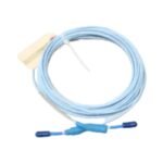
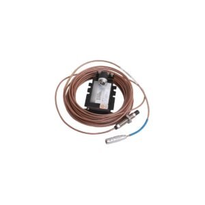
330103-00-20-10-02-00. Brand New. Original Stock. Global Shipping. Precise 8 mm proximity probe engineered for industrial vibration monitoring systems.
Configured for non-contacting vibration and position measurements in rotating machinery monitoring systems, the Bently Nevada 330103-00-20-10-02-00 (330103 Proximity Transducer) provides direct physical/electrical execution. Specifically, this primary sensing element converts mechanical displacement into a proportional electrical voltage signal. Consequently, the hardware transmits this raw proximity data to the associated 3500 series machinery protection system backplane.
Hardware Specifications
Parameter
Specification
Model
330103-00-20-10-02-00
Brand
Bently Nevada
Origin
United States
Weight
0.35 kg
Dimensions
Thread size: 3/8-24 UNF; Total length: 1.0 m
Operating Temp
-51 deg C to +177 deg C
Power Consumption
Passive sensor (powered via Proximitor Sensor loop)
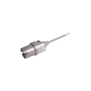
Probe Diameter
8 mm
Unthreaded Length
0.0 in
Overall Case Length
2.0 in
Total Length Option
1.0 m (3.3 ft)
Connector Option
Miniature coaxial click-loc connector with connector protector
Agency Approvals
CSA, ATEX, IECEx
Eddy-Current Probe Scaling and Rotor Dynamics
The 330103-00-20-10-02-00 projects a high-frequency eddy-current field that interacts directly with a conductive fluid-film bearing journal or shaft target surface. During mechanical inspection, engineers must validate the gap voltage to ensure it achieves a nominal -10 VDC baseline within the linear range. This calibration step establishes a standard 7.87 V/mm (200 mV/mil) scale factor. Furthermore, precise voltage alignment suppresses signal cross-talk when technicians mount multiple eddy-current probes in close proximity on the same bearing housing. Meanwhile, high-frequency rotor dynamics observations require careful physical installation to eliminate electrical and mechanical runout. Otherwise, micro-structural variations in the rotor shaft material introduce parasitic voltage fluctuations into the dynamic vibration signal waveform.
Frequently Asked Questions
Q: How does the technician establish the correct mechanical clearance during gap voltage validation?
A: The technician must mechanically position the probe until the system registers a quiescent gap voltage of -10 VDC. This value typically corresponds to approximately 1.0 mm (40 mils) of physical clearance at the center of the linear calibration envelope. Afterward, the technician tightens the locknuts to secure the position.
Q: Can the engineer connect the 1.0-meter probe cable directly to a 3500 monitoring rack without an extension cable?
A: No, because the Proximitor Sensor requires a total system electrical length of either 5.0 meters or 9.0 meters. Therefore, the engineer must utilize a matching 3300 XL extension cable to complete the transmission loop impedance circuit.
Field Installation Guidelines
Thread Engagement and Torque Limits: Mount the probe using standard 3/8-24 UNF tapped holes. Ensure a minimum thread engagement of 5 full threads so that high-frequency rotor casing vibration does not loosen the assembly. Additionally, do not exceed a maximum installation torque of 4.5 N-m (40 in-lb).
Coaxial Cable Shield Grounding: Isolate the outer shield of the miniature coaxial cable from the machine casing ground. Maintain this continuous shield isolation through the junction box up to the Proximitor Sensor terminal block. At that point, connect the shield directly to the designated instrumentation system ground point.
Minimum Target Area Clearance: Maintain a counterbore clearance diameter of at least 30 mm around the 8 mm probe tip when recessing the unit into a machine housing wall. As a result, you prevent side-view interference and distorted eddy-current fields.
Additional information
Weight
0.8 kg
Dimensions
26 × 20 × 12 mm
0.0
Average Rating
Rated
(0 Reviews)
Rated
0%
Rated
0%
Rated
0%
Rated
0%
Rated
0%
Be the first to review “Bently Nevada 330103-00-20-10-02-00 3300 XL 8 mm Proximity Transducer” Cancel reply


0.0 Average Rating Rated (0 Reviews)