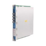
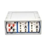
Bently Nevada TK15 80917-01 is a factory-configured Keyphasor Conditioner and Power Supply. We provide Brand New, Original Stock units with complete Global Shipping coverage.
The Bently Nevada TK15 80917-01, also cataloged as the TK15 Keyphasor Conditioner and Power Supply, operates as a dedicated hardware component for powering transducers and conditioning transducer signals within portable machinery diagnostic systems. Specifically, the instrument processes inputs from proximity sensors, velocity sensors, accelerometers, or optical pickups. Subsequently, it outputs conditioned signals for direct analysis by diagnostic hardware.
Hardware Specifications
Parameter
Specification
Model
TK15 80917-01
Brand
Bently Nevada
Origin
United States (USA)
Weight
3.1 kg (6.8 lb)
Dimensions
89 mm x 221 mm x 305 mm (3.5 in x 8.7 in x 12.0 in)
Operating Temp
0 deg C to +50 deg C
Power Consumption
95 to 125 Vac / 190 to 250 Vac switch selectable, 47 to 63 Hz
Input Channels
2 independent signal channels
Input Impedance
100 kOhm (AC coupled)
Signal Bandwidth
0.8 Hz to 30 kHz minimum
Conditioned Output
Short circuit protected, +/- 10 VDC dynamic range
Output Impedance
249 Ohm
Machinery Monitoring and TSI Characteristics
The TK15 80917-01 instrument regulates internal voltage rails and input conditioning logic to deliver precise phase reference data. To establish stable tracking of rotor dynamics, the unit interfaces directly with proximity transducers. Consequently, operators conduct gap voltage validation, targeting standard -10 VDC thresholds to confirm that connected proximity sensors remain positioned within their linear operating window. Furthermore, the internal electronic framework prioritizes cross-talk suppression by maintaining a high 100 kOhm isolation impedance across both active channel networks. This electrical barrier prevents stray inductive coupling between adjacent channels. Accordingly, the instrument converts raw voltage shifts from eddy-current probe scaling layouts into clear, uncorrupted square-wave pulse outputs that match the physical rotation of the machinery shaft.
Frequently Asked Questions
Q: How does the operator configure the primary line voltage selection for the TK15 unit?
A: The user sets the operational voltage via a mechanical slide switch located on the rear panel of the housing. Consequently, the internal transformer matches either the 95 to 125 Vac range or the 190 to 250 Vac range. The operator must verify that the installed fuse matches the voltage selection prior to applying live power.
Q: What are the specific power supply limitations when running external optical pickups from the +15 VDC supply?
A: The internal +15 VDC rail supplies a maximum total current of 150 mA. However, if the technician connects one optical pickup, the maximum allowable current drops to 100 mA. Furthermore, deploying two optical pickups simultaneously limits the remaining available current to 50 mA.
Field Installation Guidelines
Line Voltage and Fuse Verification: Before plugging the unit into an alternating current (AC) source, slide the rear voltage selector to match the local grid potential. Furthermore, confirm the presence of the correct time-delay fuse, using a 0.5 A fuse for 115 Vac setups or a 0.25 A fuse for 230 Vac setups.
Transducer Input Wiring: Terminate all raw proximity or optical sensor inputs into the front-facing coaxial BNC or multi-pin terminal points. Ensure that the external cable shields connect directly to the instrument frame ground to eliminate ambient electromagnetic noise.
Output Signal Impedance Matching: Feed the conditioned pulse outputs via the 249 Ohm short-circuit-protected jacks to the external diagnostic device. To suppress signal degradation and phase shifting, maintain interconnecting cable impedances that complement the diagnostic device inputs across the full 30 kHz bandwidth.
Physical Placement and Clearance: Position the instrument on a flat, vibration-free benchtop or secure it within a designated test enclosure. Maintain a minimum of 50 mm of unobstructed space around all case ventilation holes to permit continuous thermal dissipation during operation.
0.0
Average Rating
Rated
(0 Reviews)
Rated
0%
Rated
0%
Rated
0%
Rated
0%
Rated
0%
Be the first to review “Bently Nevada TK15 80917-01 Keyphasor Conditioner and Power Supply” Cancel reply


0.0 Average Rating Rated (0 Reviews)