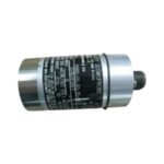
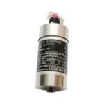
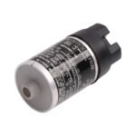
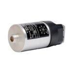
Configured for casing vibration measurements in rotating machinery, the Bently Nevada 9200-03-02-02-00 (9200 Velocity Seismoprobe Transducer) provides direct physical/electrical execution. The instrument converts mechanical casing velocity into a proportional voltage signal without requiring an external power source. It detects absolute vibration relative to free space, operating on a moving-coil design that maintains linearity across its calibrated frequency range. The output feeds directly into standard continuous monitoring systems for permanent machinery protection.
Hardware Specifications
Parameter
Specification
Model
9200-03-02-02-00
Brand
Bently Nevada
Origin
United States
Weight
0.30 kg
Dimensions
1.83 in diameter x 3.65 in length
Operating Temp
-29 deg C to +121 deg C
Power Consumption
Self-generating (0 mA external power required)
Sensitivity
20.0 mV/mm/s (500 mV/in/s) plus or minus 5%
Frequency Response
Minimum frequency range 10 Hz to 1000 Hz
Mounting Angle
0 plus or minus 100 deg (inclined upward)
Connector Type
Top-mount 2-pin Hermetic connector
Machinery Monitoring and TSI Characteristics
Because the transducer operates under stringent Turbine Supervisory Instrumentation (TSI) criteria, cross-talk suppression and internal damping dictate signal fidelity. The design avoids the eddy-current probe scaling restrictions seen in proximity systems by utilizing a spring-suspended coil moving through a permanent magnetic field. It measures structural casing vibration directly, resolving high-frequency rotor dynamics transmitted through the bearing housing. The internal suspension geometry ensures that off-axis cross-talk suppression exceeds 20:1, which prevents transverse machine case motion from corrupting the primary axis measurement path.
Frequently Asked Questions
Q: Does this velocity transducer support hot-swap replacement while the monitoring system is online?
A: Yes. Because the transducer utilizes a self-generating two-wire configuration with no external power consumption, operators can safely disconnect and replace the sensor body without powering down the monitoring backplane or risking overcurrent damage to the I/O module.
Q: What are the specific configuration limits dictated by the 03-02-02-00 suffix matrix?
A: The suffix combination defines the physical build options. The “03” designates a top-mount connector layout with a standard 100 deg upward inclination allowance, “02” selects the standard internal damping coefficient, the second “02” specifies a 1/2-20 UNF mounting thread adapter, and the final “00” indicates no multi-agency approvals.
Field Installation Guidelines
Thread Engagement and Torque: Verify that the 1/2-20 UNF mounting stud achieves at least 5 full threads of engagement into the machine casing. Torque the transducer base to exactly 6.8 N-m (60 in-lb) to prevent structural resonance shifts.
Cable Shielding and Grounding: Terminate the outer shield of the twisted-pair interconnect cable exclusively at the monitor instrument chassis ground. Leave the shield floating and isolated at the transducer end to eliminate ground loop currents.
Conduit and Routing Restrictions: Secure the flexible conduit to fixed structural supports within 300 mm of the sensor body. This prevents case-to-cable differential movement from generating mechanical noise or causing fatigue failure at the 2-pin connector termination.
Additional information
Weight
0.6 kg
Dimensions
26 × 20 × 12 mm
0.0
Average Rating
Rated
(0 Reviews)
Rated
0%
Rated
0%
Rated
0%
Rated
0%
Rated
0%
Be the first to review “Bently Nevada 9200-03-02-02-00 Two-Wire Velocity Seismoprobe Transducer” Cancel reply


0.0 Average Rating Rated (0 Reviews)