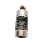
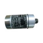
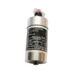
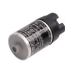
The Bently Nevada 9200-06-01-10-00, also cataloged as the 9200 Velocity Seismoprobe Transducer, operates as a dedicated hardware component for casing vibration measurements within rotating machinery monitoring systems. It translates structural casing velocity into a continuous electrical voltage signal without requiring an external excitation voltage. The internal moving-coil mass assembly detects absolute vibration relative to an inertial reference point, generating a signal that routes directly to permanent machinery protection monitors.
Hardware Specifications
Parameter
Specification
Model
9200-06-01-10-00
Brand
Bently Nevada
Origin
United States
Weight
0.30 kg
Dimensions
1.83 in diameter x 4.30 in length
Operating Temp
-29 deg C to +121 deg C
Power Consumption
Self-generating (0 mA external power required)
Sensitivity
20.0 mV/mm/s (500 mV/in/s) plus or minus 5%
Frequency Response
Minimum frequency range 10 Hz to 1000 Hz
Mounting Angle
90 plus or minus 10 deg (horizontal orientation)
Connector Type
Right-angle 2-pin Hermetic connector
Machinery Monitoring and TSI Characteristics
Because the device tracks structural casing transmission, rotor dynamics dictate the specific damping coefficients needed to accurately capture casing velocity. The moving-coil architecture allows the sensor to bypass the gap voltage validation (-10 VDC targets) needed for eddy-current probe scaling, measuring casing deflection directly rather than relative shaft position. The internal suspension system incorporates specialized oil-damping fluid to maintain stability during high-amplitude transients. Furthermore, cross-talk suppression mechanics minimize the impact of perpendicular transverse vibrations, ensuring that off-axis forces do not distort the primary horizontal measurement path.
Frequently Asked Questions
Q: What specific installation limit does the horizontal mounting orientation enforce?
A: The “06” option code configures the internal suspension spring matrix exclusively for horizontal operation (90 plus or minus 10 deg). Installing this specific model in a vertical orientation causes the internal mass to bottom out against its mechanical stops, which completely distorts the voltage output and halts data collection.
Q: How does the right-angle connector option affect field deployment?
A: The right-angle connector reduces the total clearance height required above the mounting point. This design allows operators to install the transducer inside tight machine guards or near low-clearance piping where a standard top-mount straight connector would face high risk of mechanical impact or excessive cable strain.
Field Installation Guidelines
Mounting Torque and Engagement: Ensure the mounting adapter achieves a minimum of 5 full threads of engagement into the bearing housing. Tighten the transducer base to exactly 6.8 N-m (60 in-lb); undertorquing creates an artificial mechanical attenuation filter, while overtorquing distorts the sensor case.
Shielding and Isolation Isolation: Run the twisted-pair signal wire through a dedicated, grounded metal conduit. Connect the overall cable shield to the instrumentation ground terminal at the monitoring rack only, and leave the shield floating at the sensor end to prevent ground loop interference.
Cable Strain Relief: Implement a drip loop in the flexible conduit immediately adjacent to the right-angle connector housing. This loop isolates the electrical termination pins from structural casing strain and prevents condensed environmental moisture from collecting inside the plug assembly.
Additional information
Weight
1 kg
Dimensions
26 × 20 × 28 mm
0.0
Average Rating
Rated
(0 Reviews)
Rated
0%
Rated
0%
Rated
0%
Rated
0%
Rated
0%
Be the first to review “Bently Nevada 9200-06-01-10-00 Two-Wire Velocity Seismoprobe Transducer” Cancel reply


0.0 Average Rating Rated (0 Reviews)