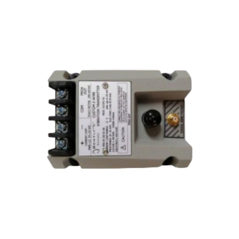
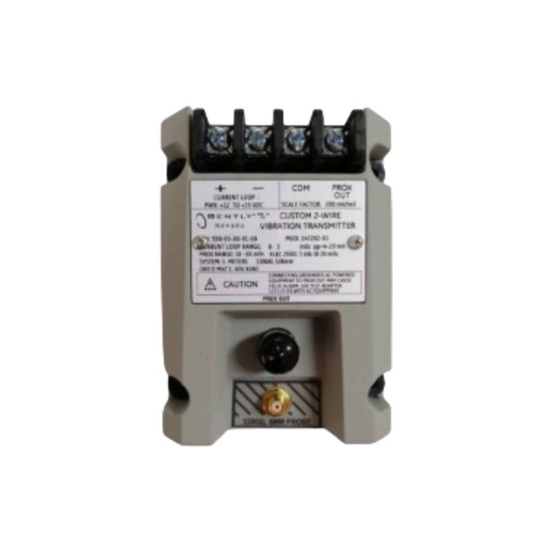
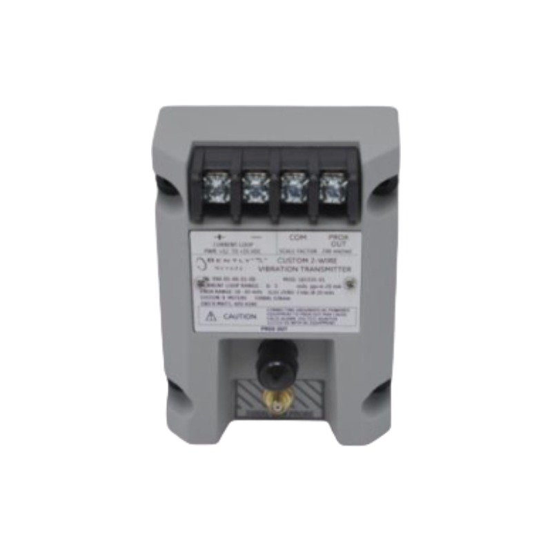
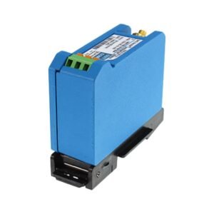
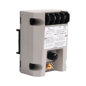
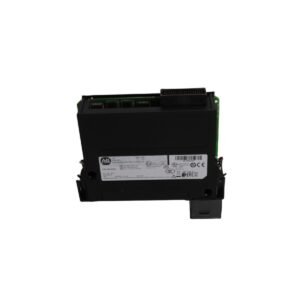
The Bently Nevada 990-10-XX-01-05 serves as the primary 990 Vibration Transmitter utilized to execute non-contacting radial vibration measurements across machine monitoring platforms. Specifically, the transmitter conditions high-frequency electrical signals from an eddy-current probe system and subsequently modulates a linear 4-20 mA current loop proportional to the peak-to-peak vibration amplitude. Consequently, this design executes the direct delivery of dynamic machinery metrics to distributed control systems (DCS) or programmable logic controllers (PLC) without requiring an intermediate monitoring rack.
Hardware Specifications
Parameter
Specification
Model
990-10-XX-01-05
Brand
Bently Nevada
Origin
USA
Weight
0.28 kg (0.62 lbs)
Dimensions
81.3 mm x 61.2 mm x 50.8 mm
Operating Temp
-35 deg C to +85 deg C
Power Consumption
Less than 1.0 W nominal
Input Signal
3300 NSv Proximity Probe and Extension Cable
Output Signal
4-20 mA DC (Linear peak-to-peak vibration scaled)
System Supply Voltage
12 to 35 VDC at the transmitter terminal
Mounting
35 mm DIN-rail clips
Eddy-Current Probe Scaling and Transducer Dynamics
The Bently Nevada 990-10-XX-01-05 utilizes precise eddy-current probe scaling to convert physical gap fluctuations into high-frequency electrical signals for the analysis of dynamic rotor dynamics. During commissioning, engineers perform gap voltage validation (-10 VDC targets) within the specified linear operational range, thereby verifying the proper probe-to-target alignment. Furthermore, the internal electronics deploy integrated cross-talk suppression circuitry; as a result, the hardware minimizes electromagnetic interference even when multiple sensor lines run through parallel wire conduits.
Frequently Asked Questions
Q: What does the “05” suffix signify in the agency approval position of the model number?
A: The “05” suffix indicates multiple global hazardous area approvals, including specific ATEX, IECEx, and CSA certifications for deployment in Class I, Division 2 or Zone 2 environments.
Q: How does the “Not OK/Signal Defeat” circuit operate during a sensor failure?
A: If a loose connection or damaged cable occurs, the internal circuit detects the fault and automatically drives the 4-20 mA loop current below 3.6 mA. Consequently, this prevents false high-vibration alarms within the control system.
Field Installation Guidelines
Shielding and Grounding: First, terminate the coaxial extension cable shield securely at the transmitter housing terminal block. Afterward, ground the overall 4-20 mA field wiring shield at a single point inside the control room instrument panel to mitigate ground loop noise.
Conduit Separation: Always route all sensor proximity probe leads and transmitter current loop cables inside dedicated, isolated metal conduits. In addition, avoid running signal wiring parallel to high-voltage AC lines or variable frequency drive (VFD) paths.
Mechanical Orientation: Install the transmitter housing on a standard 35 mm DIN rail or, alternatively, bolt it directly to a flat panel. For installations in environments with high humidity or chemical exposure, mount the assembly inside an enclosure rated IP54 or higher.
Additional information
Weight
0.28 kg
Dimensions
65 × 70 × 85 mm
0.0
Average Rating
Rated
(0 Reviews)
Rated
0%
Rated
0%
Rated
0%
Rated
0%
Rated
0%
Be the first to review “Bently Nevada 990-10-XX-01-05 Vibration Transmitter” Cancel reply











0.0 Average Rating Rated (0 Reviews)