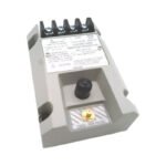
990-04-XX-01-00. Brand New. Original Stock. Global Shipping. Loop-powered 2-wire vibration transmitter providing direct 4-20 mA output for PLC/DCS systems.
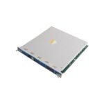
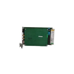
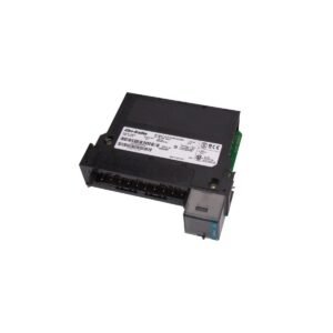
Configured for relative vibration measurement on rotating machinery, the Bently Nevada 990-04-XX-01-00 (990 Vibration Transmitter) provides direct physical/electrical execution. This 2-wire, loop-powered device accepts input directly from a non-contacting 3300 NSv proximity probe and matching extension cable assembly. Consequently, the internal circuitry conditions the proximity signal into a proportional 4-20 mA analog output representing peak-to-peak vibration amplitude for direct integration into plant PLC or DCS platforms.
Suffix Breakdown & Model Matrix
990: Core product identifier for the 2-wire, loop-powered Vibration Transmitter series.
04: Full-scale vibration amplitude measurement range option designated as 0-4 mils pp (0-100 um pp).
XX: Variable placeholder for total system electrical length configuration; options dictate either 50 (5.0 meters) or 70 (7.0 meters).
00: Factory agency approval certification level option denoting standard build with no specific hazardous area certifications required.
Hardware Specifications
Parameter
Specification
Model
990-04-XX-01-00
Brand
Bently Nevada
Origin
United States
Weight
0.43 kg
Dimensions
81.3 mm x 61.2 mm x 103.4 mm
Operating Temp
-40 deg C to +80 deg C
Power Consumption
Loop-powered, +12 VDC to +35 VDC input at terminals
Output Signal
4-20 mAdc proportional to full-scale vibration
Loop Accuracy
Within +/- 1.5% over specified full-scale range
Maximum Loop Resistance
1000 Ohm at 35 VDC input
Transducer Compatibility
1 non-contacting 3300 NSv Proximity Probe loop
Frequency Response
5 Hz to 6000 Hz (+0 dB, -3 dB)
Mounting Base
Integrated 35 mm DIN-rail mount pattern
Eddy-Current Probe Scaling and Rotor Dynamics
The 990-04-XX-01-00 incorporates internal Proximitor conditioning circuitry that energizes the connected 3300 NSv probe to generate a high-frequency eddy-current field. During mechanical installation, loop validation requires setting a target baseline gap voltage via the raw PROX OUT test signal terminal. Furthermore, because this device drives compact 3300 NSv probes, it provides robust cross-talk suppression inside tight centrifugal air compressor housings where multiple sensing elements operate close to one another. Technicians must align the installation carefully to avoid interference from electrical or mechanical shaft runout. Otherwise, micro-structural shaft variations deform the eddy-current flux lines, which injects parasitic noise into the 4-20 mA output and obscures real-time rotor dynamics.
Frequently Asked Questions
Q: How does a technician access the raw dynamic vibration signal for diagnostic analysis on this transmitter?
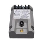
A: The transmitter includes a front-facing, ungrounded coaxial BNC connector labeled PROX OUT. This interface outputs a continuous 7.87 mV/um (200 mV/mil) raw voltage signal, enabling field operators to connect portable oscilloscopes or data collectors without disrupting the primary 4-20 mA control loop.
Q: What action does the transmitter loop take if the associated 3300 NSv probe cable snaps or disconnects?
A: The device features an integrated Not OK/Signal Defeat circuit. If a probe fault or loose connection occurs, the internal circuit triggers instantly and forces the 4-20 mA loop current down to less than 3.6 mA within 100 microseconds. This action prevents false high-vibration trips inside the control system logic.
Field Installation Guidelines
Probe Gapping Procedure: Mechanically adjust the 3300 NSv probe body inside its mounting bracket until the voltage reading at the transmitter PROX OUT terminal registers a quiescent value corresponding to the center of the linear envelope. The acceptable baseline gap window spans between 0.5 mm and 1.75 mm (20 to 55 mils) relative to the shaft target surface.
Wiring and Loop Impedance Balancing: Connect a twisted-pair shielded cable to the positive and negative transmitter terminals. Ensure total loop resistance, including field wiring and the DCS input card internal resistance, does not exceed 1000 Ohm when operating from a 35 VDC supply loop. Ground the cable shield exclusively at the control room end.
Target Area Clearance Dimensions: Verify that the observed shaft target area provides a minimum flat surface diameter of 9.5 mm (0.375 in). If the shaft target area is smaller than this minimum requirement, the eddy-current field will experience edge-effect degradation, causing permanent calibration errors.
Additional information
Weight
0.6 kg
Dimensions
32 × 16 × 20 mm
0.0
Average Rating
Rated
(0 Reviews)
Rated
0%
Rated
0%
Rated
0%
Rated
0%
Rated
0%
Be the first to review “Bently Nevada 990-04-XX-01-00 990 Vibration Transmitter” Cancel reply


0.0 Average Rating Rated (0 Reviews)