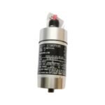
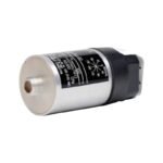
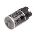
Obtain the original Bently Nevada 9200-01-01-01-00 two-wire moving-coil velocity seismoprobe transducer. We provide brand new, original stock factory parts with global shipping options for your immediate machinery protection upgrades.
The Bently Nevada 9200-01-01-01-00, also cataloged as the 9200 Seismoprobe Velocity Transducer, operates as a dedicated hardware component for absolute casing vibration measurement within machinery protection and structural monitoring networks. Specifically, the two-wire electromechanical sensor utilizes internal moving-coil technology to translate physical casing or bearing housing velocity into a proportional analog voltage signal without requiring external excitation power.
Suffix Breakdown & Model Matrix
Code Segment
Definition
9200
Standard Temperature Two-Wire Seismoprobe Transducer
Standard Unregulated Environment (No Agency Approvals)
Hardware Specifications
Parameter
Specification
Model
9200-01-01-01-00
Brand
Bently Nevada
Origin
United States
Weight
300 g (10.5 oz) typical
Dimensions
41 mm Diameter x 102 mm Height
Operating Temp
-29 to 121 deg C
Power Consumption
Passive Device (Self-generated EMF via moving coil)
Electrical Sensitivity
20 mV/mm/s (500 mV/in/s) +/- 5% at 100 Hz
Frequency Response
4.5 Hz to 1.0 kHz (+0, -3 dB typical)
Internal Coil Resistance
1.25 kOhm +/- 5%
Maximum Shock Resistance
50 g peak along non-sensitive transverse axis
Rotor Dynamics and Transducer Conditioning
To achieve highly precise rotor dynamics and casing structural analysis, this passive transducer incorporates specialized electromechanical components that require accurate downstream monitor scaling. Because this specific configuration dictates a vertical orientation (-01 mounting option), the internal moving-coil suspension requires precise vertical alignment to preserve the absolute linear velocity baseline. Integration with Bently Nevada 3300 or 3500 monitoring racks requires validation of gap voltage targets, typically maintained at -10 VDC for adjacent proximity probes sharing the same machinery train. This complete sensor layout enables accurate tracking of 1X and 2X structural vibration vectors. Furthermore, the robust physical construction ensures cross-talk suppression between neighboring sensors. As a result, the hardware maintains sharp signal separation and clear waveform transmission even when technicians mount multiple seismic units in high-density structural clusters.
Frequently Asked Questions
Q: Does this velocity sensor require an external power supply or loop-powered driver?
A: No. The internal moving-coil design operates completely passively, meaning the physical mechanical vibration generates an independent electromotive force (EMF) voltage output directly proportional to casing velocity.
Q: What happens if an installer misaligns the vertical mounting angle by more than 2.5 degrees?
A: Exceeding the 0 deg +/- 2.5 deg mounting limit causes internal coil friction against the permanent magnet assembly. Consequently, this mechanical drag dampens low-frequency sensitivity and introduces severe measurement distortion below 10 Hz.
Q: What is the maximum allowable field wiring distance between the 9200 transducer and the receiving rack?
A: Technicians can extend interconnecting field wiring up to a maximum length of 305 meters (1000 feet). However, installers must deploy high-quality shielded, twisted-pair cabling to actively eliminate electromagnetic interference across the loop.
Field Installation Guidelines
Mechanical Torque and Stud Engagement: Mount the transducer base onto a flat, rigid surface machined perpendicular to the primary vibration axis. Ensure the 1/4-20 UNC threaded stud engages a minimum of 5 full threads into the casing, and tighten the assembly to a strict torque specification of 5.6 N-m (50 in-lb) to prevent mechanical resonance.
Shield Termination: Route the two-wire output signal using dedicated shielded cable assemblies. Terminate the outer shield drain wire exclusively at the receiving monitor rack chassis ground, while leaving the field-side shield floating and completely insulated inside the junction box to eliminate ground loops.
Electrical Polarity Verification: Connect terminal Pin A and Pin B according to the system wiring diagram. Under standard operating conditions, Pin A goes positive with respect to Pin B whenever the machine casing moves physically toward the top connector assembly.
Additional information
Weight
0.3 kg
Dimensions
70 × 100 × 60 mm
0.0
Average Rating
Rated
(0 Reviews)
Rated
0%
Rated
0%
Rated
0%
Rated
0%
Rated
0%
Be the first to review “Bently Nevada 9200-01-01-01-00 Seismoprobe Velocity Transducer” Cancel reply


0.0 Average Rating Rated (0 Reviews)