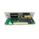
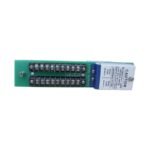
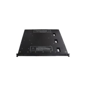
The Bently Nevada 88149-01 operates as a dedicated hardware component for physical relay contact execution within Bently Nevada 3300 Series Monitoring Systems.
Hardware Specifications
Parameter
Specification
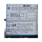
Model
88149-01
Brand
Bently Nevada
Origin
United States
Weight
0.22 kg
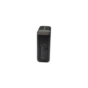
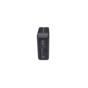
Dimensions
Standard 3300 backplane footprint
Operating Temp
-35 deg C to +65 deg C
Power Consumption
2.0 W maximum
Module Type
Alarm Relay Outputs Assembly
Relay Configurations
Alert and Danger (Normal / Failsafe)
Eddy-Current Probe Scaling and Rotor Dynamics Integrity
The Bently Nevada 88149-01 processes the discrete hardware logic that converts transducer measurements into definitive machinery trip actions. Therefore, during routine system validation, field technicians execute eddy-current probe scaling and confirm gap voltage validation (-10 VDC targets) at the front monitor cards, while this rear-facing assembly manages the mechanical relay states. Because high-frequency rotor dynamics generate complex electrical waves across the backplane, the board traces incorporate internal cross-talk suppression paths. Consequently, these structural isolation barriers prevent adjacent phase trigger signals or vibration card inputs from causing accidental contact closure or corrupted alarm status changes.
Frequently Asked Questions
Q: Does the 88149-01 assembly allow hot-swapping while the 3300 rack remains powered?
A: No. Removing or inserting the rear relay assembly while power flows through the backplane can cause transient voltage spikes across the data lines. Consequently, this action may trigger false machine trips or cause component damage, meaning technicians must fully isolate the rack power first.
Q: How can an operator configure the 88149-01 relay outputs to behave in a failsafe mode?
A: Technicians change the operational mode by manipulating the physical hardware jumpers located directly on the assembly circuit board. Specifically, configuring the jumper to a de-energize-to-trip state ensures the contacts change state instantly if the system loses input power.
Field Installation Guidelines
Verify Wire Termination Torque: Secure all field wiring lines into the terminal screw links using a calibrated torque screwdriver. Specifically, maintain a tightening torque of exactly 0.5 Nm (4.4 in-lbs) to avoid loose connections from structural machine vibration.
Isolate External Power Loops: Keep all external alarm indicator or solenoid control wiring physically separate from the low-voltage sensor cables. Therefore, route these high-current paths through a different conduit junction path to mitigate inductive coupling risks.
Observe Minimum Bend Metrics: Manage all multi-conductor alarm output cables inside the rear wire ducts by enforcing a strict minimum bend radius of 50.8 mm (2.0 inches) to prevent core wire stress.
Additional information
Weight
0.22 kg
Dimensions
70 × 26 × 38 mm
0.0
Average Rating
Rated
(0 Reviews)
Rated
0%
Rated
0%
Rated
0%
Rated
0%
Rated
0%
Be the first to review “Bently Nevada 88149-01 Alarm Relay Outputs Assembly Module” Cancel reply


0.0 Average Rating Rated (0 Reviews)