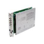
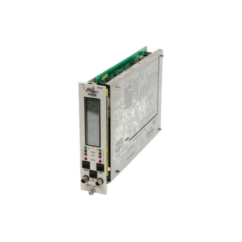
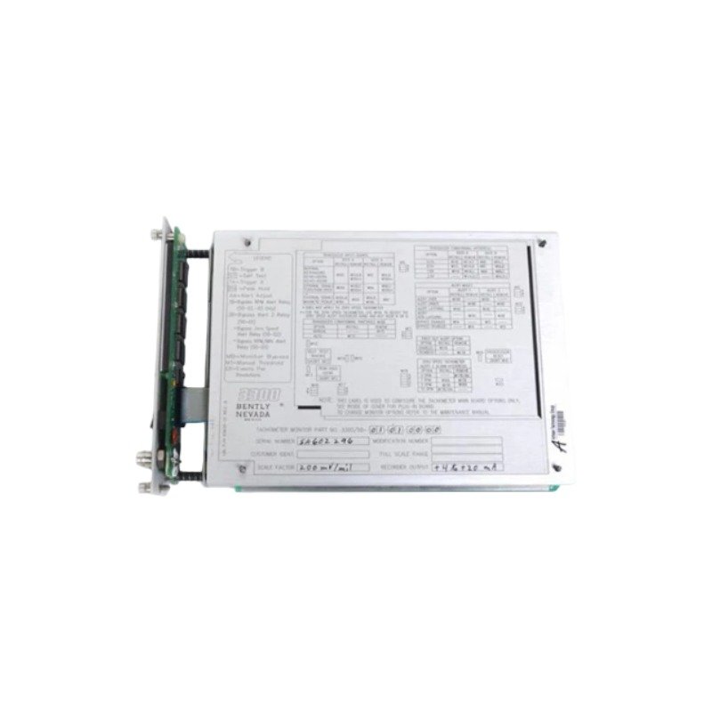
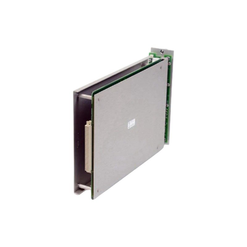
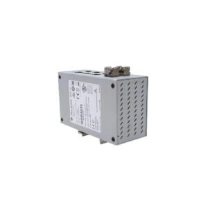
The Bently Nevada 79482-01 is a 3300 series dual thrust position monitor featuring 24 VDC supply and 0 to 10 kHz frequency response. Brand New, Original Stock, Global Shipping.
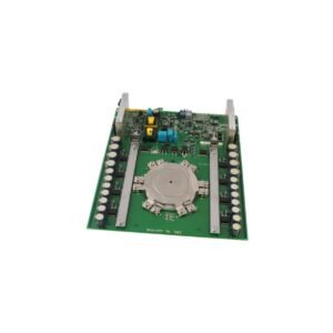
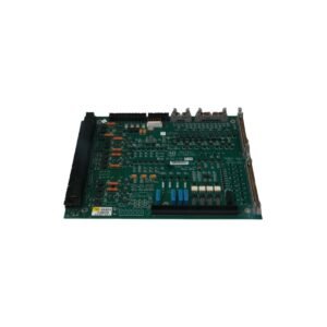
Configured for axial shaft movement and dynamic displacement monitoring in machine protection frameworks, the Bently Nevada 79482-01 (79482-01 Dual Thrust Position Monitor) provides direct physical/electrical execution. Specifically, this module processes transducer input signals across two independent channels to measure thrust positioning relative to reference baselines. Furthermore, the localized circuitry interfaces with 3300 series sensors, handling continuous voltage operations and converting raw analog tracking metrics into real-time safety metrics to execute fast trip sequences before bearing or seal breakdown occurs.
Hardware Specifications
Parameter
Specification
Model
79482-01
Brand
Bently Nevada
Origin
USA
Weight
2.8 kg
Dimensions
33.0 cm x 20.3 cm x 5.7 cm
Operating Temp
0 deg C to +65 deg C
Power Consumption
24 VDC Transducer Power Supply
Input Signal Range
+10.0 V to -24.0 V
Voltage Compliance
0 to +12 VDC
Output Resistance
50 Ohm
Output Impedance
100 Ohm (Voltage Outputs)
Extension Cable Capacitance
69.9 pF/m
Field Wiring Range
0.2 to 1.5 mm2
Minimum Target Size
15.2 mm
Frequency Response
0 to 10 kHz
Machinery Monitoring and TSI Characteristics
This dual thrust position monitor board executes automated diagnostics to maintain the baseline calibration parameters necessary for eddy-current probe scaling configurations. The internal processing channels perform continuous gap voltage validation (-10 VDC targets) across the proximity probe loops to verify structural health before assessing shaft displacement. Because the unit samples across a high-frequency response range from 0 to 10 kHz, the system architecture utilizes internal low-pass filtering to guarantee cross-talk suppression. Consequently, this prevents localized electromagnetic interference from distorting the low-voltage analog inputs during high-velocity rotor dynamics transients.
Frequently Asked Questions
Q: How does the extension cable capacitance specification affect the total calibrated loop length?
A: The module relies on a specific internal calibration matched to an extension cable capacitance of 69.9 pF/m. Deviating from the specified cable length or electrical capacitance skews the probe scaling matrix, which compromises the accuracy of the thrust position telemetry.
Q: What physical reaction occurs within the module if the transducer input voltage drifts outside the +10.0 V to -24.0 V window?
A: The monitor instantly flags an out-of-bounds tracking anomaly, illuminating the channel NOT OK status lamp. This internal hardware mechanism locks out the alarm logic to prevent a false machinery trip caused by external wire failures.
Q: Can this thrust monitor accept direct input from standard moving-coil seismic velocity sensors?
A: No, this hardware option conditions DC proximity probe signals for axial displacement tracking. Velocity sensors require distinct AC-coupled processing channels found on alternative vibration monitoring cards.
Field Installation Guidelines
Mounting Mechanics: Insert the monitor module assembly straight into the designated rack chassis allocation. Next, tighten all front panel securing fasteners to establish a rigid ground bond capable of dampening continuous low-frequency plant vibration.
Shielding Requirements: Terminate all incoming sensor cable shields at the dedicated instrument terminal strip ground bus. Ensure the field-side transducer shield remains completely ungrounded to prevent electrical ground loop interference.
Wiring Separations: Route the field wiring conductors (0.2 to 1.5 mm2) away from high-current AC motor leads or noisy variable frequency drive cables. Maintain a minimum separation barrier of 300 mm to protect the low-voltage signal paths.
Thermal Management: Verify that cabinet louvers or cooling blocks maintain ambient air parameters within the specified 0 deg C to +65 deg C limits. Avoid blocking the module faceplate paths to prevent localized thermal component drift.
Additional information
Weight
2.80 kg
Dimensions
65 × 74 × 77 mm
0.0
Average Rating
Rated
(0 Reviews)
Rated
0%
Rated
0%
Rated
0%
Rated
0%
Rated
0%
Be the first to review “Bently Nevada 79482-01 Dual Thrust Position Monitor” Cancel reply










0.0 Average Rating Rated (0 Reviews)