Purchase the Bently Nevada 3500/53 overspeed monitoring module. Available as Brand New, Original Stock with rapid Global Shipping dispatch loops worldwide.
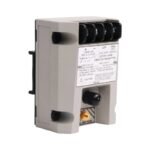
The Bently Nevada 3500/53, also cataloged as the 3500/53 Overspeed Detection Module, operates as a dedicated hardware component for emergency machine shutdown execution within a 3500 Machinery Protection System. Configured for high-speed rotational monitoring, the module processes sensor inputs from magnetic pickups or proximity probes to deliver direct physical activation of trip relays when shaft velocity exceeds designated safety setpoints.
Hardware Specifications
Parameter
Specification
Model
3500/53
Brand
Bently Nevada
Origin
USA
Number of Channels
3 independent speed input channels
Input Sensors
Magnetic Pickups, 3300 XL Proximity Transducers
Response Time
15 milliseconds maximum
System Architecture
2-out-of-3 (2oo3) voting logic matrix
Relay Outputs
3 onboard dedicated overspeed trip relays
Weight
0.85 kg
Dimensions
241.3 mm x 24.4 mm x 241.8 mm
Operating Temp
-30 to +65 deg C
Power Consumption
8.0 W typical under full channel configuration
Eddy-Current Probe Scaling and Rotor Dynamics
The solid-state processing engine maintains localized electronic parameters to track instantaneous peak velocities during transient machine acceleration events. When engineers interface this module with displacement sensors, the internal threshold circuits execute constant gap voltage validation relative to the target -10 VDC baseline, ensuring precise eddy-current probe scaling. This precise input conditioning drives rapid trigger logic across the whole rotor dynamics spectrum. Furthermore, the specialized backplane layout isolates the signal pathways, maintaining aggressive cross-talk suppression between channels to prevent stray electromagnetic field noise from generating false overspeed trip pulses.
Frequently Asked Questions
Q: How does the 2-out-of-3 (2oo3) internal architecture affect overall trip reliability?
A: The 2oo3 voting logic requires at least two of the three independent physical channels to register an overspeed condition before triggering the trip relays. Consequently, this arrangement prevents a single sensor failure from causing an accidental machine shutdown while ensuring safety redundancy.
Q: Can an engineer calibrate the overspeed setpoints while the turbine is online?
A: No, modifying safety critical trip limits requires the user to place the module into Program Mode via the physical front panel keylock. Changing these parameters online introduces serious safety risks, so the hardware locks out software configuration edits during active machine operation.
Field Installation Guidelines
Chassis Insertion Mechanics: Slide the main module into the designated front rack slot until the upper and lower latching arms click closed. Secure the matching I/O module into the rear position directly behind the main unit, hand-tightening all captive screws.
Sensor Wire Routing Constraints: Keep all speed sensor input lines physically separated from high-voltage motor power leads or variable frequency drive wiring. Maintain a minimum clearance distance of 305 mm inside all shared wireways to suppress transient pulse coupling.
Shield Grounding Isolation: Terminate the transducer field cable shields exclusively at the dedicated chassis earth bars on the rear terminal block. Never ground the shield at the field junction box or sensor casing, thereby eliminating hazardous ground loop paths.
Additional information
Weight
0.85 kg
Dimensions
60 × 210 × 60 mm
0.0
Average Rating
Rated
(0 Reviews)
Rated
0%
Rated
0%
Rated
0%
Rated
0%
Rated
0%
Be the first to review “Bently Nevada 3500/53 Electronic Overspeed Detection System” Cancel reply


0.0 Average Rating Rated (0 Reviews)