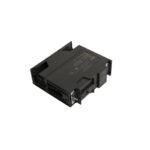
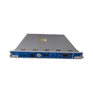
The Bently Nevada 3500/22-01-03-01 is a Transient Data Interface CPU Module with a fiber optic I/O sub-assembly. Available Brand New, Original Stock with Global Shipping.
Configured for multi-channel machinery data acquisition in 3500 Machinery Protection System platforms, the Bently Nevada 3500/22-01-03-01 (3500/22 Transient Data Interface Module) provides direct physical/electrical execution. The instrument integrates static, dynamic, and high-resolution transient waveforms from all connected monitor cards to route data directly to external network software hosts.
Hardware Specifications
Parameter
Specification
Model
3500/22-01-03-01
Brand
Bently Nevada
Origin
United States
Weight
0.91 kg (TDI Main Board); 0.20 kg (I/O Board)
Dimensions
241.3 x 24.4 x 241.8 mm
Operating Temp
-30 to +65 deg C
Power Consumption
10.5 watts nominal
Interface Type
01: Standard Transient Data Interface
I/O Configuration
03: 100Base-FX Fiber-Optic Ethernet I/O module
Agency Approvals
01: CSA/NRTL/C (Class 1, Division 2, Groups A, B, C, D)
Communications
Front Panel USB-B (115.2 kbaud maximum); Rear Fiber-Optic (MT-RJ Female)
OK Relay Rating
5 A @ 24 VDC / 120 VAC maximum
Eddy-Current Probe Scaling and Rotor Dynamics
The module processes systemic machinery profiles derived from eddy-current probe scaling, compiling synchronous and asynchronous wave data across up to 48 concurrent channels. Field optimization demands validation of continuous proximity tracking paths, ensuring that baseline gap voltage validation (-10 VDC targets) stays uniform during rapid speed transitions. The integrated 100Base-FX fiber optic sub-assembly enforces isolated cross-talk suppression between high-frequency telemetry backplanes and external plant distribution grids, securing phase-accurate tracking of rotor dynamics up to 100,000 rpm.
Frequently Asked Questions
Q: What structural impact does the 3500/22-01-03-01 module have on the critical automatic machine protection trip path?
A: The module manages communications, system configuration, and diagnostic data streaming to external clients; it is not part of the active machinery protection path and does not interfere with individual monitor hardware relay tripping functions.
Q: How do the front-panel indicator LEDs identify the monitoring mode status of the chassis?
A: The module contains four distinct front-panel status indications: OK LED shows internal processor state, TX/RX LED denotes active backplane module communications, TM LED registers active Trip Multiply status, and CONFIG OK confirms the baseline file checksum matches the physical module array.
Field Installation Guidelines
Seat the main processor assembly strictly in Slot 1 of the 3500 chassis frame, directly adjacent to the power supply module slot.
Clean the rear optical port sockets with anhydrous optical solvents before coupling the MT-RJ fiber termination connector.
Turn the front-panel configuration keylock to RUN mode after configuration parameters are uploaded to prevent accidental runtime register edits.
Separate the external Ethernet network cabling paths from local raw power routing runs to mitigate potential inductive signal distortions.
Torquing both upper and lower slot retaining fasteners is mandatory to complete the chassis ground continuity link to the frame.
Additional information
Weight
0.91 kg
Dimensions
60 × 70 × 80 mm
0.0
Average Rating
Rated
(0 Reviews)
Rated
0%
Rated
0%
Rated
0%
Rated
0%
Rated
0%
Be the first to review “Bently Nevada 3500/22-01-03-01 Transient Data Interface Module” Cancel reply


0.0 Average Rating Rated (0 Reviews)