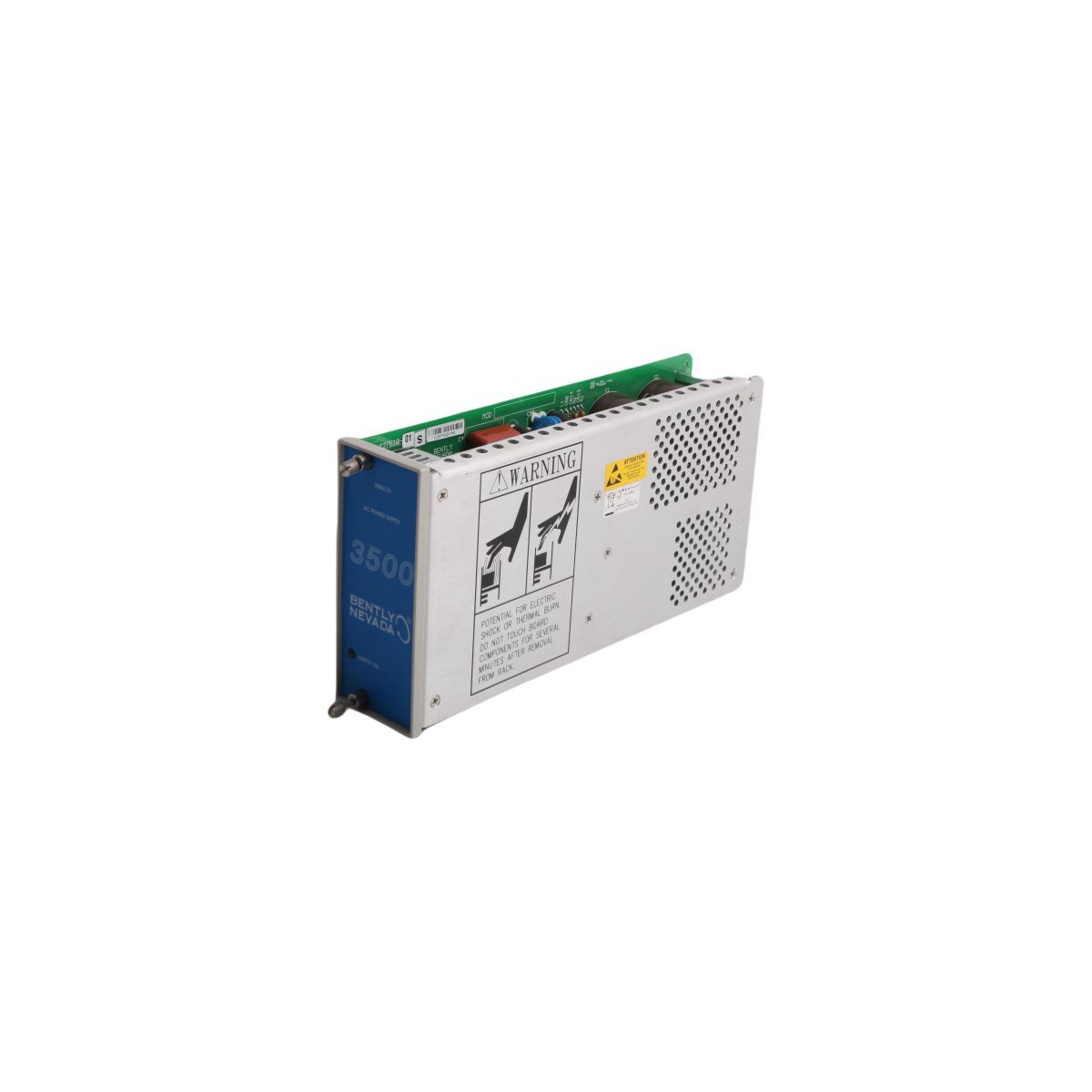
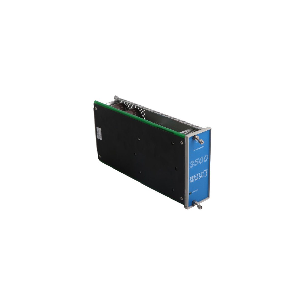
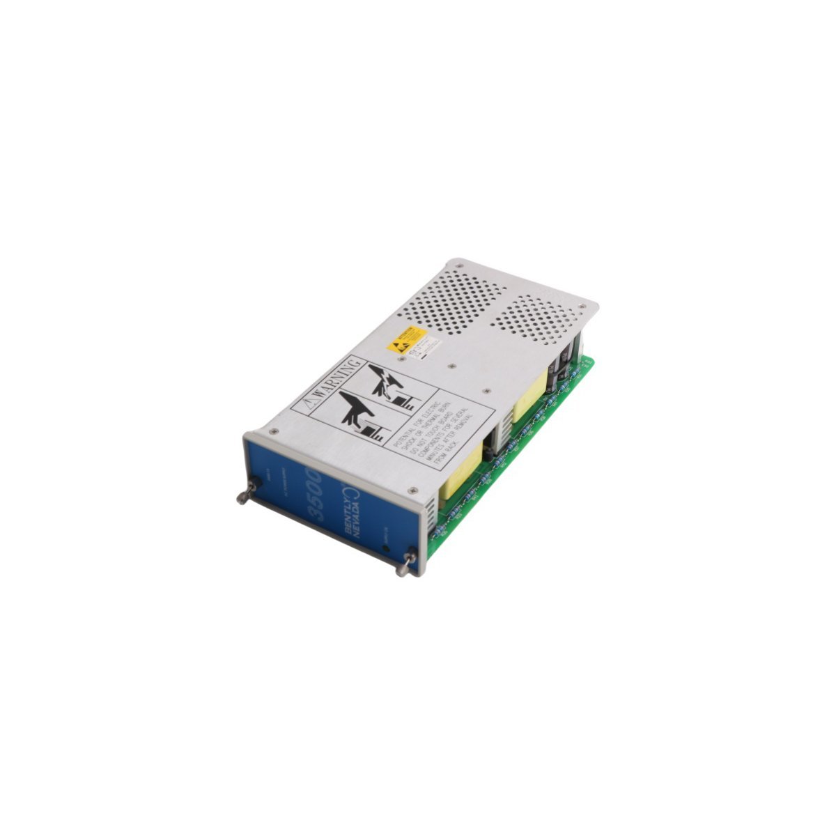
The 3500/15-01-01-00 is a dual-redundant legacy AC Power Supply module configured for 3500 series machinery protection racks. We maintain Brand New, Original Stock with Global Shipping.
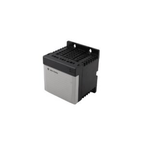
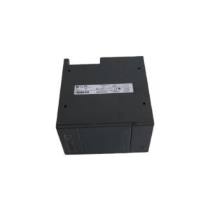
The Bently Nevada 3500/15-01-01-00 serves as the primary 3500/15 Power Supply Module utilized to execute continuous voltage conversion and regulation across Bently Nevada 3500 System Rack platforms. This specific half-height internal component populates the dedicated power supply bays on the left side of the chassis. By converting external incoming lines into stabilized direct current distribution rails, the hardware energizes the shared backplane logic, bus communication paths, and field transducer loops, which enforces deterministic hardware execution under demanding plant conditions.
Suffix Breakdown & Model Matrix
The specific alphanumeric option codes determine the exact module type, redundant channel assignment, and regional safety approvals chosen for this power supply assembly:
3500/15: Base catalog identification for the half-height, chassis-mounted machinery protection power supply system.
-01: Specifies a Legacy High Voltage AC Power Supply configuration designed to operate on nominal 110 V or 220 V line distributions (uses the 127610-01 internal board assembly).
-01: Designates a Legacy High Voltage AC Power Supply option in the alternate slot position, establishing a matching redundant architecture.
-00: Standard non-hazardous agency approval layer without localized safety barrier installations or hazardous zone certificates.
Hardware Specifications
Parameter
Specification
Model
3500/15-01-01-00
Brand
Bently Nevada
Origin
USA
Weight
1.39 kg
Dimensions
50.80 mm x 120.70 mm x 251.50 mm
Operating Temp
-30 deg C to +65 deg C
Power Consumption
250 W maximum input capacity
High AC Input Limits
175 to 264 VAC rms
Low AC Input Limits
85 to 132 VAC rms
Input Frequency
47 to 63 Hz
Peak Volts Threshold
373 VAC pk
Redundancy Switching Latency
Less than 2 microseconds
Machinery Monitoring and TSI Characteristics
The Bently Nevada 3500/15-01-01-00 enforces rigid electrical stability for delicate Turbine Supervisory Instrumentation (TSI) circuits. The onboard high-frequency transformer array integrates heavy internal shielding to maintain strict cross-talk suppression between neighboring slots hosting high-gain vibration, speed, and position tracking cards. When routing regulated current across the rack backplane, the unit pins its secondary output reference directly to the main chassis frame, preserving precise gap voltage validation against the targeted -10 VDC baseline mandatory for accurate eddy-current proximity probe tracking. This filtering configuration isolates raw line switching noise, preventing ripple voltages from distorting high-speed rotor dynamics data such as shaft centerline paths and sub-synchronous vibration phases.
Frequently Asked Questions
Q: Can the 3500/15-01-01-00 power supply pair with a newer 106M1081-01 Universal AC Power Input Module?
A: No. The -01-01 suffixes denote the legacy high-voltage AC configuration. This specific hardware variant is physically and electrically incompatible with the newer universal series and must pair strictly with legacy 125840-01 High Voltage AC rear Power Input Modules (PIMs).
Q: What happens if an operator extracts one of the active power cards during system operation?
A: Because the -01-01 code establishes a dual-redundant matching hardware pair, the lower card acts as the primary and the upper as the backup. Operators can safely hot-swap either card without disrupting system telemetry, as the remaining module inherits the total rack load within 2 microseconds.
Field Installation Guidelines
Chassis Insertion: Slide the 3500/15-01-01-00 supply module firmly along the left-hand slot guides of the 3500 rack until its blind-mate connectors engage fully with the backplane pins. Tighten both front-panel captive retention screws to 0.56 Nm (5 in-lb) to resist industrial structural vibrations.
Chassis Grounding Loop Prevention: Connect a low-impedance copper earthing lead (minimum 4 mm squared cross-section) directly from the rear PIM grounding stud to the main plant instrumentation earth network. Do not run this earth lead in parallel with high-voltage motor or variable frequency drive ground lines.
Input Cable Termination: Strip back the single-phase field wiring cables exactly 7 mm, secure them inside the terminal clamping blocks on the corresponding rear PIM, and verify screw tightness reaches 0.56 Nm (5 in-lb) to eliminate erratic contact faults.
Additional information
Weight
1.39 kg
Dimensions
260 × 120 × 60 mm
0.0
Average Rating
Rated
(0 Reviews)
Rated
0%
Rated
0%
Rated
0%
Rated
0%
Rated
0%
Be the first to review “Bently Nevada 3500/15-01-01-00 Power Supply Module” Cancel reply











0.0 Average Rating Rated (0 Reviews)