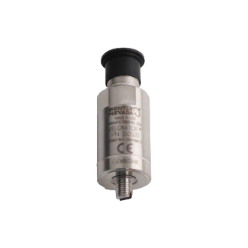
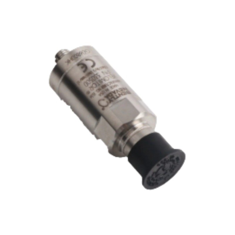
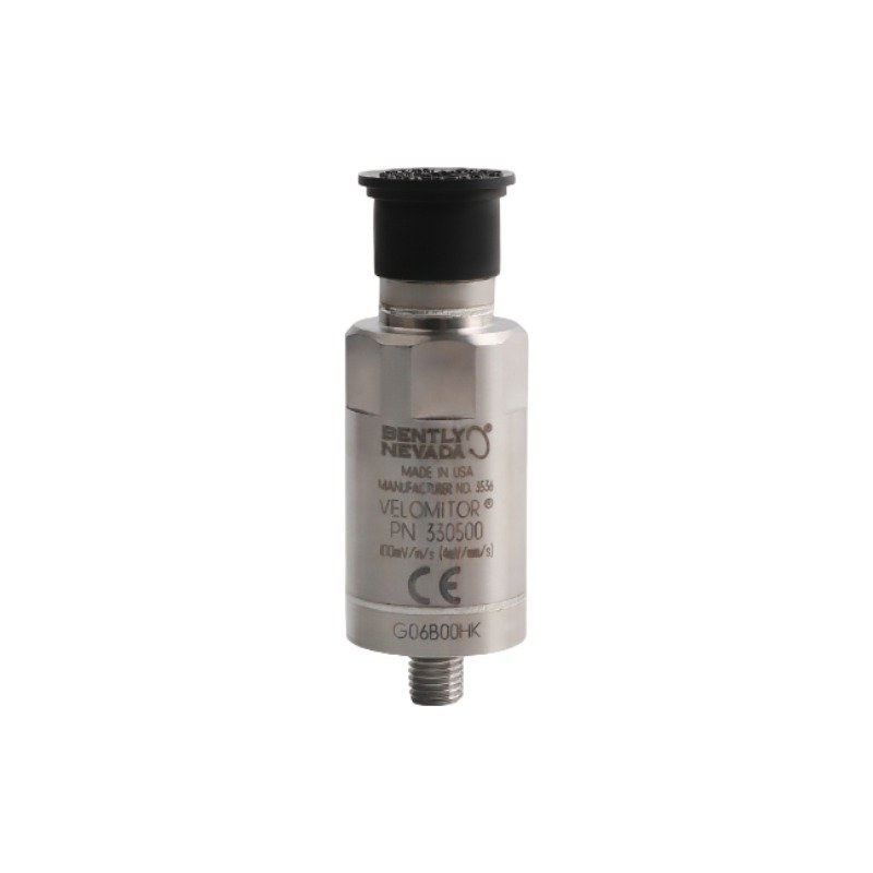
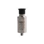
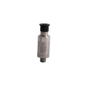
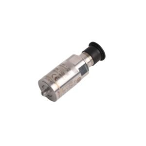
The Bently Nevada 330500-04-00 serves as the primary 330500 Velomitor Piezo-velocity Sensor utilized to execute non-contacting casing velocity measurements across machinery monitoring platforms. Specifically, the internal piezoelectric crystal network senses case acceleration and integrates the physical response into a proportional velocity signal. Consequently, the electronic circuitry converts these mechanical vibrations into an analog current or voltage format. Finally, the module transmits these vibration transitions directly to connected machinery protection systems to track absolute structural dynamic behavior.
Threaded stud engagement via 1/4 – 20 UNC interface
Machinery Monitoring & Rotor Dynamics Integration
The sensor mechanism operates by evaluating casing structural response parameters directly correlated with high-speed rotor dynamics. Furthermore, signal conditioning hardware paths apply specific filter parameters to isolate critical machine frequencies while preventing electronic interference. This configuration allows clean tracking of vibration velocity baselines across the specified operating band. As a result, this baseline allows accurate recording of physical casing transitions during peak cyclic loads. In addition, built-in structural balancing architecture provides cross-talk suppression between adjacent sensor units mounted perpendicularly along the same machinery bearing housing.
Frequently Asked Questions
Q: Can this sensor function correctly if installed using a 1/4-18 NPT thread profile adapter?
A: No. Suffix option -04 dictates a factory machined 1/4 – 20 UNC thread configuration. Therefore, changing the thread profile requires ordering a dedicated 330525 series variant to ensure proper mechanical engagement and tight structural coupling.
Q: Is this velocity sensor designed to support active hot-swapping under live loop power?
A: No. The internal piezoelectric integration electronics lack static current limiters for hot attachment. Consequently, you must isolate loop power before connecting or disconnecting the field interface plug to prevent electrical component failure.
Field Installation Guidelines
For mechanical installation, thread the sensor base directly into the prepared mounting hole surface. Meanwhile, ensure the integrated mounting thread engages completely to achieve maximum surface contact and resist physical attenuation from high-frequency operational machine vibrations. You must also mount the housing shell away from direct moisture accumulation to maintain internal sensor environment conditions within the specified boundaries of -55 deg C to +121 deg C.
Regarding electrical connections, insert the dedicated connector plug cleanly into the top receptacle interface. Concurrently, tighten the threaded coupling nut securely without applying excessive torque that could crack the internal contact points. Furthermore, route all shielded multi-conductor cables away from high-voltage alternating current distribution lines, variable frequency drives, and heavy inductive switchgear to avoid electromagnetic coupling. Finally, terminate the overall instrumentation outer shield exclusively at the monitoring rack’s dedicated system ground terminal block to prevent ground-loop current circulation.
Additional information
Weight
0.14 kg
Dimensions
65 × 70 × 75 mm
0.0
Average Rating
Rated
(0 Reviews)
Rated
0%
Rated
0%
Rated
0%
Rated
0%
Rated
0%
Be the first to review “Bently Nevada 330500-04-00 Velomitor Piezo-velocity Sensor” Cancel reply















0.0 Average Rating Rated (0 Reviews)