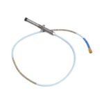
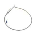
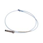
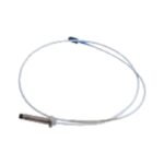
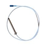
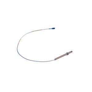
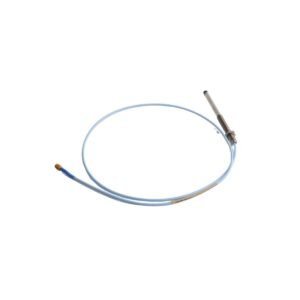
Obtain the original Bently Nevada 330103-00-05-10-02-00 3300 XL 8 mm proximity probe with M10 x 1 threads. We provide brand new, original stock parts with global shipping options for your immediate machinery protection upgrades.
Configured for non-contact shaft displacement and dynamic vibration measurement in fluid-film bearing machinery, the Bently Nevada 330103-00-05-10-02-00 (330103 3300 XL 8 mm Proximity Probe) provides direct physical/electrical execution. Specifically, the probe generates a high-frequency electromagnetic field around its tip to interact with a conductive metal target, and it subsequently feeds a raw modulated radio frequency (RF) signal back to a companion Proximitor sensor to track micro-inch surface variations instantaneously.
Suffix Breakdown & Model Matrix
Code Segment
Definition
330103
3300 XL 8 mm Proximity Probe, M10 x 1 metric thread, without armor
-00
Unthreaded Length Option: 0 mm
-05
Overall Case Length Option: 50 mm
-10
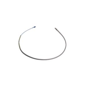
Total Length Option: 1.0 meter (3.3 feet)
-02
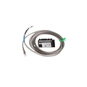
Connector and Cable Type Option: Miniature coaxial ClickLoc connector, standard cable
-00
Agency Approval Option: No hazardous area certifications required
Hardware Specifications
Parameter
Specification
Model
330103-00-05-10-02-00
Brand
Bently Nevada
Origin
United States
Weight
0.35 kg (0.77 lbs)
Dimensions
M10 x 1 Thread, 50 mm Case Length, 1.0 m Total Cable Length
Operating Temp
-34 to 177 deg C
Power Consumption
Passive element (Excited via remote -24 VDC Proximitor)
Linear Range
2.0 mm (80 mils) nominal
Scale Factor Sensitivity
7.87 V/mm (200 mV/mil) when combined with 3300 XL system
Probe Tip Material
Polyphenylene Sulfide (PPS)
Rotor Dynamics and Transducer Conditioning
To achieve highly precise rotor dynamics analysis, this metric eddy-current sensor requires stable downstream tuning that actively handles transducer scaling. During setup, the physical deployment demands strict gap voltage validation, targeting a nominal -10 VDC offset (approx. 1.0 mm or 40 mils physical gap) to place the signal within the absolute center of the linear calibration envelope. This tight operating boundary prevents signal clipping and simultaneously maximizes the dynamic resolution of high-frequency transient voltage swings during rapid acceleration phases. Furthermore, patented TipLoc and CableLoc molding technologies supply robust cross-talk suppression by locking structural components into a high-strength bond that resists 330 N (75 lbf) of mechanical pull force. As a result, the hardware maintains sharp pulse-edge tracking and minimal phase-amplitude noise even when engineers operate the probe near high-density magnetic fields.
Frequently Asked Questions
Q: Does this proximity probe require physical matching or custom calibration with its specific extension cable?
A: No. The 3300 XL system establishes complete interchangeability across all probes, extension cables, and Proximitor sensors, allowing technicians to replace components without performing bench-level field calibration.
Q: What physical indicator confirms that the miniature coaxial connector is correctly seated?
A: The gold-plated brass ClickLoc coaxial connectors incorporate an integrated mechanical locking layout. This mechanism emits an audible click during hand-tightening, which confirms the assembly is secure against machinery vibration.
Q: What happens if moisture or cutting fluids enter the coaxial connection point?
A: Fluid ingress shifts the high-frequency line impedance away from the calibrated 75 Ohm base value. Consequently, this mismatch de-calibrates the average scale factor and alters the baseline gap voltage readings.
Field Installation Guidelines
Mechanical Torque and Thread Engagement: Screw the probe into the threaded machine housing bracket using a calibrated torque wrench. Do not exceed the maximum allowable installation torque limit of 13.5 N-m (120 in-lb) to actively safeguard the internal coil bonds from structural stress.
Shield Termination: Route the probe cable straight to the junction box container. Terminate the outer extension cable shields exclusively at the receiving monitor rack chassis ground, while keeping the field-side probe shield floating and fully insulated inside the local housing to eliminate ground loops.
Minimum Target Boundaries: Mount the probe tip at a physical distance of at least 13 mm (0.5 in) away from adjacent structural walls or counterbores. This physical spacing allows the electromagnetic field to form without encountering side-view interference patterns.
Additional information
Weight
0.35 kg
Dimensions
220 × 120 × 80 mm
0.0
Average Rating
Rated
(0 Reviews)
Rated
0%
Rated
0%
Rated
0%
Rated
0%
Rated
0%
Be the first to review “Bently Nevada 330103-00-05-10-02-00 Proximity Probe Module” Cancel reply


0.0 Average Rating Rated (0 Reviews)