Technical properties, option code breakdown, and electrical parameters for the Bently Nevada 3300/55 dual velocity monitor. Available as Brand New, Original Stock with Global Shipping.
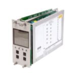
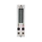
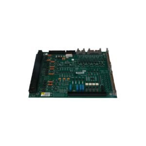
The Bently Nevada 3300/55-03-04-14-14-00-00-04-00, also cataloged as the Bently Nevada 3300/55 Dual Velocity Monitor, operates as a dedicated hardware component for continuous casing vibration tracking within 3300 Series Machinery Protection System networks. The module accepts velocity-proportional analog signals from two independent field transducers simultaneously, executing onboard mathematical integration to derive structural displacement metrics. Consequently, the monitoring platform drives deterministic emergency alarm trip relays to safeguard industrial rotating assets without introducing processing cycle latency into the critical protective loop.
Suffix Breakdown & Model Matrix
Option Code
Specification Selection
03
Channel Input Option: Both channels active, configured for displacement integration
04
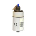
Transducer Type Option: Configured for Velomitor Transducer (100 mV/in/s)
14
Channel A Full-Scale Range: 0 to 100 micrometers peak-to-peak (pp)
14
Channel B Full-Scale Range: 0 to 100 micrometers peak-to-peak (pp)
00
Agency Approval Option: None / Standard unclassified
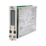
The dual-channel transmitter interface incorporates specialized signal conditioning circuits to execute internal signal integration, translating raw velocity inputs into precise peak-to-peak displacement metrics. Therefore, the integrated hardware supports rapid transducer bias verification to achieve continuous gap voltage validation (-10 VDC targets) and sensor fault isolation across active loops. Furthermore, the specialized trace distribution layout achieves strict cross-talk suppression between proximal signal input pathways. As a result, this design isolates adjacent vibration tracking links to preserve raw telemetry integrity during the assessment of high-speed rotor dynamics.
Frequently Asked Questions
Q: Can maintenance personnel perform online hot-swap operations with this dual velocity monitor?
A: Yes, this hardware accommodates physical insertion and extraction while the host 3300 rack chassis remains under live electrical power. However, because removing the module immediately severs the active safety interlock loops, operators must engage the channel bypass switches prior to removal to eliminate the risk of false plant trips.
Q: How do the quad relays react when an alert or danger threshold is breached?
A: The onboard epoxy-sealed relays actuate deterministically based on independent channel setpoint evaluations. Consequently, the internal logic triggers separate alert and danger dry contacts for Channel A and Channel B, allowing engineers to route independent warning signals up to localized safety networks.
Field Installation Guidelines
Slide the half-height module firmly into its designated slot track within the 3300 rack chassis, verifying full connector seat engagement with the system backplane.
Torque the front panel retention hardware to a fixed specification of 0.6 N-m to maintain robust structural frame continuity and functional grounding.
Keep low-voltage Velomitor signal cables strictly segregated from parallel alternating current power conduits by a minimum clearance of 300 mm to suppress inductive noise coupling.
Terminate all incoming field sensor coaxial shields at the designated terminal block grounding strip, enforcing a strict single-point grounding framework to eliminate common-mode ground loops.
Additional information
Weight
0.98 kg
Dimensions
320 × 80 × 60 mm
0.0
Average Rating
Rated
(0 Reviews)
Rated
0%
Rated
0%
Rated
0%
Rated
0%
Rated
0%
Be the first to review “Bently Nevada 3300/55-03-04-14-14-00-00-04-00 Dual Velocity Monitor” Cancel reply


0.0 Average Rating Rated (0 Reviews)