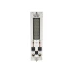
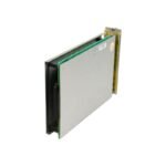
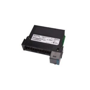
The Bently Nevada 3300/50-02-02-00-00, also cataloged as the 3300/50 Tachometer Monitor, operates as a dedicated hardware component for continuous rotational machinery speed processing within machinery protection systems. Specifically, the system receives high-frequency voltage pulses from proximity probes or magnetic pickups, thereby converting those raw timing signals into a real-time digital RPM display, rotor acceleration parameters, or dedicated zero-speed state variables.
Suffix Breakdown & Model Matrix
The complete alphanumeric product code structures the specific hardware selection factory-installed into this tachometer monitoring block assembly:
Option Field
Ordered Suffix Code
Functional Component Definition
Tachometer Type
02
Zero Speed Tachometer configuration (tracks thresholds < 100 RPM)
Alert Relay
02
5 Amp Hermetically-sealed alarm relay module
Agency Approval
00
None / Standard non-hazardous safe area classification
Safety Barrier
00
No internal zener barriers configured
Hardware Specifications
Parameter
Specification
Model
3300/50-02-02-00-00
Brand
Bently Nevada
Origin
USA
Weight
1.5 kg
Dimensions
5.1 cm x 20.3 cm x 33.0 cm
Operating Temp
-20 to +65 deg C
Power Consumption
2.5 W nominal
Signal Inputs
Accepts up to 2 independent transducer inputs (Proximity or Magnetic Pickups)
7-segment character LCD with continuous parameter readout
Slot Requirements
Occupies any single standard monitor slot in a 3300 rack
Machinery Monitoring and Transducer Interface Dynamics
The processing hardware executes real-time eddy-current probe scaling to accurately translate physical displacement into precise electrical potentials. Consequently, gap voltage validation enforces an operational baseline of -10 VDC for standard proximity sensors, which ensures that the transducer maintains its linear range during high-frequency rotor dynamics observations. Furthermore, dynamic signal isolation circuitry constrains cross-talk suppression to under -60 dB across adjacent measurement paths, thereby preventing electrical resonance interference from corrupting critical vibration calculations.
Frequently Asked Questions
Q: How does the internal dual-transducer voting logic mitigate sensor failures?
A: The monitor processes incoming speed signals from two independent probes observing the same target. Next, internal validation logic matches the pulse frequency across both lines; if a single transducer fails or loses its pulse thread, the internal engine suppresses a false zero-speed alarm and flags an individual channel OK fault.
Q: Can an engineer utilize this specific 3300/50 module configuration for emergency turbine overspeed trip protection?
A: No, Bently Nevada design regulations explicitly state that standard 3300/50 modules do not possess the rapid response speeds or triple-modular redundancy required for high-speed protective tripping control. Consequently, operators must use this component strictly for data logging, indicator panel viewing, or low-priority annunciator alarming.
Field Installation Guidelines
Field Wiring and Shield Terminal Isolation: Wire the transducer coaxial extension cables directly to the rear backplane terminal block assignment. Next, isolate the outer shield braid completely at the probe junction box, and then terminate the drain wire only at the designated rack ground bar to block induced magnetic field noise loops.
Magnetic Pickup Airgap Optimization: Maintain a rigid, mechanical clearance window between the magnetic pickup tip and the targeted gear tooth pattern if utilizing passive sensors. In doing so, lock the threaded barrel tight against its mounting frame to ensure the sensor creates high-amplitude voltage transitions even at low rotational startup speeds.
Module Retaining Screw Engagement: Slide the monitor firmly along the guide tracks until the edge connectors lock flush with the backplane pin field. Afterwards, torque the upper and lower captive panel fasteners to establish full chassis ground bonding across the aluminum enclosure front plate.
Additional information
Weight
1.50 kg
Dimensions
65 × 85 × 95 mm
0.0
Average Rating
Rated
(0 Reviews)
Rated
0%
Rated
0%
Rated
0%
Rated
0%
Rated
0%
Be the first to review “Bently Nevada 3300/50 Tachometer Monitor Module” Cancel reply


0.0 Average Rating Rated (0 Reviews)