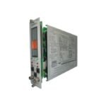
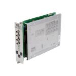
The Bently Nevada 3300/20-12-01-02-00-00, also cataloged as the 3300/20 Dual Thrust Position Monitor, operates as a dedicated hardware component for continuous axial shaft movement tracking within machinery protection systems. Specifically, the module processes DC voltage variations from two independent proximity probe transducers, thereby translating these changes into direct physical shaft displacement measurements relative to the thrust bearing face and generating proportional 4-20 mA recorder outputs.
Suffix Breakdown & Model Matrix
The complete alphanumeric product code structures the specific hardware selection factory-installed into this thrust positioning block assembly:
Option Field
Ordered Suffix Code
Functional Component Definition
Full-Scale Range
12
50-0-50 mils full-scale scale configuration
Transducer Type
01
3300 or 7200 8mm Proximity Transducer Systems
Agency Approval
02
ATEX / BASEEFA self-certified intrinsically safe zone classification
Intrinsically Safe
00
No internal zener barriers configured
Output Option
00
Standard 4-20 mA DC analog recorder loop outputs
Relay Option
00
No individual channel relays installed (utilizes rack common relays)
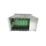
Occupies any single standard monitor slot in a 3300 rack
Machinery Monitoring and Transducer Interface Dynamics
The processing hardware executes real-time eddy-current probe scaling to accurately translate physical displacement into precise electrical potentials. Consequently, gap voltage validation enforces an operational baseline of -10 VDC for standard proximity sensors, which ensures that the transducer maintains its linear range during high-frequency rotor dynamics observations. Furthermore, dynamic signal isolation circuitry constrains cross-talk suppression to under -60 dB across adjacent measurement paths, thereby preventing electrical resonance interference from corrupting critical vibration calculations.
Frequently Asked Questions
Q: How does the 3300/20 monitor handle dual-channel voting for critical machinery trip interlocks?
A: When integrated into the common rack backplane, the system allows the option for 1oo2 or 2oo2 hardware voting configurations. Under 2oo2 logic, both axial probes must simultaneously breach the Danger setpoint boundary, which drastically minimizes false machinery trips caused by isolated sensor mechanical damage.
Q: What precise diagnostic action occurs when an axial probe moves beyond its linear calibration range?
A: The monitor constantly scans the input DC bias level. If a physical shift pushes the gap voltage outside the internal -2.0 VDC to -18.0 VDC diagnostic window, the internal logic drops the channel OK relay, illuminates the front panel “NOT OK” LED, and automatically locks out the associated safety alarm circuits.
Field Installation Guidelines
Field Wiring and Shield Terminal Isolation: Wire the transducer coaxial extension cables directly to the rear backplane terminal block assignment. Next, isolate the outer shield braid completely at the probe junction box, and then terminate the drain wire only at the designated rack ground bar to block induced magnetic field noise loops.
Probe Mechanical Gap Centering: Mount the physical thrust proximity probes looking at an integral shaft shoulder or the shaft end. During machine standstill, mechanical adjustments must position the probe to read exactly the zero-center electrical voltage baseline, which matches the chosen 50-0-50 mil span option.
Module Retaining Screw Engagement: Slide the monitor firmly along the guide tracks until the edge connectors lock flush with the backplane pin field. Afterwards, torque the upper and lower captive panel fasteners to establish full chassis ground bonding across the aluminum enclosure front plate.
Additional information
Weight
1.00 kg
Dimensions
50 × 60 × 70 mm
0.0
Average Rating
Rated
(0 Reviews)
Rated
0%
Rated
0%
Rated
0%
Rated
0%
Rated
0%
Be the first to review “Bently Nevada 3300/20 Dual Thrust Position Monitor” Cancel reply


0.0 Average Rating Rated (0 Reviews)