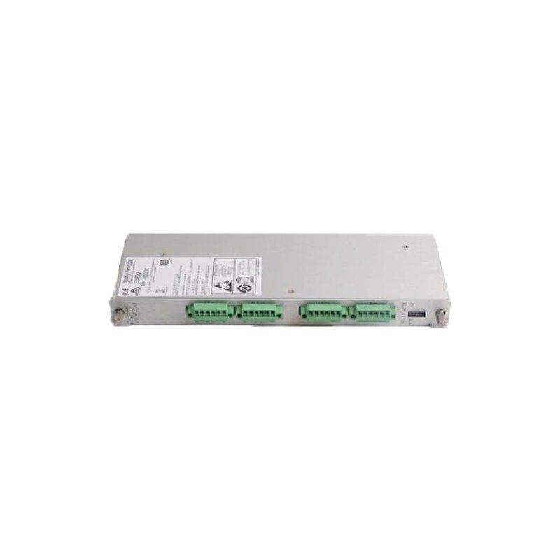
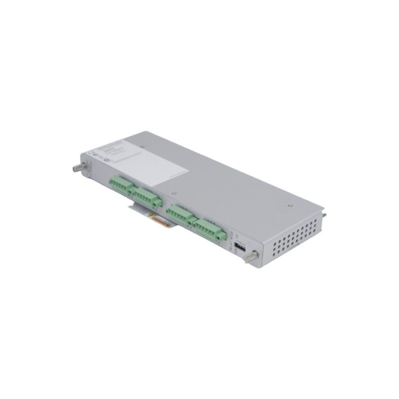
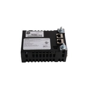
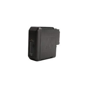
Configured for shaft speed, vibration amplitude, and phase angle measurement in the 3500 Machinery Protection System, the Bently Nevada 103928-02 (103928-02 Keyphasor KPH Input Board) provides direct physical/electrical execution. The hardware acquires high-resolution pulse timing data to compute angular reference information relative to the physical rotation of machine shafts. Raw conditioning metrics are buffered locally and subsequently routed across dedicated digital backplane paths toward network-accessible infrastructure.
Hardware Specifications
Parameter
Specification
Model
103928-02
Brand
Bently Nevada
Origin
USA
Weight
700 g
Dimensions
406.4 mm x 304.8 mm x 254.0 mm (16.0 x 12.0 x 10.0 inches)
Operating Temp
-30 deg C to +65 deg C
Power Consumption
7 W typical
Key Measurements
Shaft speed, vibration amplitude, phase angle
Integrated Memory
Two independent startup/shutdown transient buffers
Communication Interface
Ethernet link to Data Manager
Data Formats
High-resolution static, orbit, and spectrum data
Machinery Monitoring and TSI Characteristics
The input conditioning channel topology enforces rigorous eddy-current probe scaling to translate phase reference pulses generated by proximity transducers into clean square-wave triggers. Internal tracking components execute continuous gap voltage validation (-10 VDC targets) across the hardware inputs to maintain proper probe-to-target distance calibration metrics. By compiling real-time pulse edges, the logic isolates precise rotor dynamics, outputting high-resolution static, orbit, and spectrum datasets. Furthermore, high-attenuation cross-talk suppression circuitry isolates adjacent instrumentation paths, preventing sharp transient Keyphasor trigger pulses from generating electrical inductive noise across low-amplitude vibration signal channels.
Frequently Asked Questions
Q: How do the two independent startup/shutdown buffers manage high-resolution transient datasets?
A: The onboard non-volatile memory matrix partition allocates separate, isolated storage arrays specifically to capture continuous speed, orbit, and spectrum data during mechanical speed transitions, preserving data integrity in the event of an upstream network failure.
Q: Can the Ethernet link to the Data Manager be utilized for primary system-wide hardware configuration changes?
A: The built-in Ethernet communication pathway serves as a high-throughput diagnostic conduit to stream static and dynamic variables to host software. Configuration modifications require connection through the proper rack interface module security switch.
Q: What are the primary installation prerequisites concerning input trigger thresholds?
A: The hardware logic requires an incoming voltage change that crosses the predefined hysteresis limits. Technicians must configure proper signal attenuation and threshold levels within the system software to prevent double-triggering caused by minor shaft surface scratches.
Field Installation Guidelines
Mounting Mechanics: Insert the board assembly directly into its assigned slot along the rear panel of the 19-inch 3500 rack system. Secure all retention screws completely to ensure proper chassis ground continuity and rigid physical anchoring against vibration.
Shielding Requirements: Run all Keyphasor transducer field cables using dedicated twisted-shielded pairs or coaxial media. Terminate the outer copper shield element solely at the rack system instrument ground bus bar, leaving the field sensor side ungrounded.
Wiring Separations: Keep low-voltage Keyphasor pulse circuits and Ethernet communication cables at a distance of at least 200 mm from high-voltage AC lines and variable-frequency drive motor supply cables to prevent electromagnetic interference.
Thermal Management: Verify that the internal enclosure environment remains within the -30 deg C to +65 deg C limits. Maintain continuous vertical airflow across the card surface area by checking that the chassis ventilation slots remain unobstructed.
Additional information
Weight
0.70 kg
Dimensions
95 × 70 × 65 mm
0.0
Average Rating
Rated
(0 Reviews)
Rated
0%
Rated
0%
Rated
0%
Rated
0%
Rated
0%
Be the first to review “Bently Nevada 103928-02 Keyphasor KPH Input Board” Cancel reply












0.0 Average Rating Rated (0 Reviews)