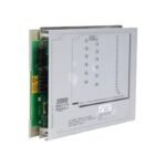
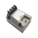
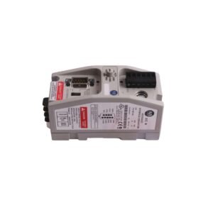
Configured for continuous vibration monitoring on rotating machinery assemblies, the Bently Nevada 990-08-XX-03-00 (990 Vibration Transmitter) provides direct physical/electrical execution.
Suffix Breakdown & Model Matrix
The configured options specify full-scale range parameters, physical integration scale, mounting hardware layout, and regulatory compliance paths:
08 (Full-scale Option): Establishes a peak-to-peak displacement range of 0-8 mils pp (0-200 um pp).
XX (System Length Option): Denotes a variable field placeholder for system length selection, which dictates either 50 (5.0 meters) or 70 (7.0 meters) matched cable constraints.
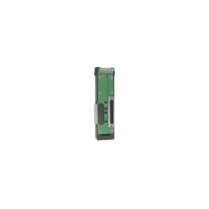
03 (Mounting Option): Combines 35 mm DIN rail clips and bulkhead mounting screws into a unified hardware package.
00 (Agency Approval Option): Declares no hazardous area approvals requested.
Hardware Specifications
Parameter
Specification
Model
990-08-XX-03-00
Brand
Bently Nevada
Origin
USA
Weight
0.43 kg
Dimensions
117 mm x 44 mm x 44 mm
Operating Temp
-35 to +85 deg C
Power Consumption
12 to 35 VDC loop-powered (2-wire interface)
Signal Output
Proportional 4-20 mA current loop
Loop Accuracy
Within +/- 1.5% over full-scale range
Frequency Response
5 Hz to 6000 Hz (+0 dB, -3 dB limits)
Target Compatibility
Calibrated for 3300 NSv proximity probes
Machinery Monitoring and TSI Characteristics
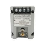
The integrated loop-powered circuit translates high-frequency eddy-current probe scaling data directly into an analog current infrastructure. Therefore, the transmitter delivers steady loop operation by managing an internal gap voltage validation curve, which requires probe gapping between 0.5 mm and 1.75 mm from the observed shaft surface. The standalone design also incorporates a dedicated coaxial “PROX OUT” terminal, which isolates a raw, non-inverted dynamic signal with a 7.87 mV/um scale factor to track raw rotor dynamics. Consequently, internal filtering schemes activate a Not OK/Signal Defeat circuit that instantly drops loop output below 3.6 mA during probe faults, while built-in cross-talk suppression keeps nearby compressor lines from inducing noise into the current measurement.
Frequently Asked Questions
Q: What behavior occurs during system power-up to prevent control system trip errors?
A: An integrated Power-up Inhibit circuit holds the loop output below 3.6 mA for 2 to 3 seconds following voltage application. Consequently, this delay blocks line transients from triggering premature machinery alarms.
Q: How do operators verify transmitter function without spinning the actual machinery shaft?
A: Field engineers inject an AC signal from a standard function generator into the designated Test Input pin. Therefore, this action drives the 4-20 mA loop proportionally to verify loop scaling accuracy.
Field Installation Guidelines
Secure the device baseplate to the enclosure interior using the supplied 35 mm DIN rail clips or bulkhead screws. To maintain appropriate current loop regulation, verify that total loop resistance stays below 1000 ohms when operating at the maximum 35 VDC input threshold. Run the 75-ohm coaxial cable from the 3300 NSv probe through isolated, grounded metal conduits to block electromagnetic interference. Finally, ensure that the potted transmitter body avoids fluid submergence, though its fully sealed housing withstands up to 100% condensing humidity environments.
Additional information
Weight
0.6 kg
Dimensions
26 × 16 × 22 mm
0.0
Average Rating
Rated
(0 Reviews)
Rated
0%
Rated
0%
Rated
0%
Rated
0%
Rated
0%
Be the first to review “Bently Nevada 990-08-XX-03-00 990 Vibration Transmitter” Cancel reply


0.0 Average Rating Rated (0 Reviews)