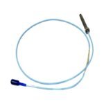
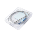
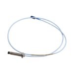
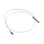
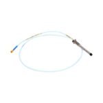
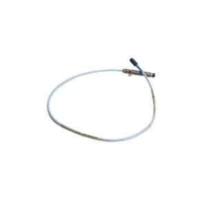
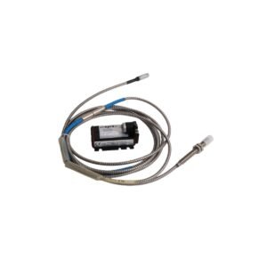
Bently Nevada 330103-00-06-10-02-CN is a 3300 XL 8mm metric proximity probe. Factory new original stock available with certificates of conformance for immediate global transport.
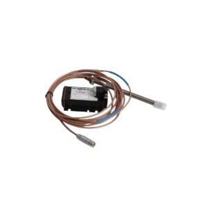
Configured for dynamic vibration and position tracking in rotating machinery, the Bently Nevada 330103-00-06-10-02-CN (330103 Proximity Probe) provides direct physical/electrical execution. It functions as a non-contacting transducer element within critical machinery protection platforms.
Suffix Breakdown & Model Matrix
The alphanumeric suffix codes define specific physical dimensions, structural features, and certification parameters for the assembly:
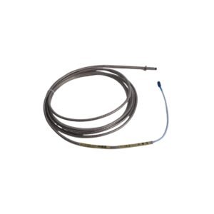
330103: 3300 XL 8 mm Proximity Probe with M10 x 1 metric thread, without mechanical armor.
00: Unthreaded length option specifying 0 mm of clear case barrel.
06: Overall case length option specifying a 60 mm total threaded barrel.
10: Total length option denoting a 1.0 meter (3.3 feet) integrated cable.
02: Connector and cable-type option indicating standard cable terminated with a miniature coaxial ClickLoc connector.
CN: Agency approval option dictating country-specific certifications for explosive or regulated hazardous environments.
Hardware Specifications
Parameter
Specification
Model
330103-00-06-10-02-CN
Brand
Bently Nevada
Origin
United States (USA)
Weight
0.13 kg (0.29 lbs)
Dimensions
M10 x 1 thread, 60 mm case length, 1.0 m cable length
Operating Temp
-51 deg C to +177 deg C (-60 deg F to +350 deg F)
Power Consumption
Passive sensor element (excitation drawn from external Proximitor)
Linear Range
2.0 mm (80 mils), beginning at 0.25 mm (10 mils) from probe tip
Scale Factor
7.87 V/mm (200 mV/mil) nominal when calibrated against 4140 steel
Probe Tip Material
Polyphenylene sulfide (PPS)
Probe Case Material
AISI 303 or 304 stainless steel (SST)
Machinery Monitoring and TSI Characteristics
The 330103-00-06-10-02-CN probe deploys a precise eddy-current coil structure to monitor continuous rotor dynamics on fluid-film bearing machines. The drive electronics from a coupled Proximitor establish a high-frequency RF field at the tip, which reacts directly to displacement variations of the observed conductive surface. Field setup requires systematic gap voltage validation, where field technicians establish a mechanical offset targeting -10 VDC to baseline the system within its optimized linear zone. Strict physical layout criteria must be managed to maintain cross-talk suppression between multiple co-located probes, ensuring that overlapping electromagnetic fields do not distort the low-level signal paths returned to the TSI chassis.
Frequently Asked Questions
Q: How does the “CN” agency approval affect the physical wiring of the probe installation?
A: The CN designation dictates compliance with specific local country regulatory guidelines for hazardous areas. The internal electrical parameters remain standard, but the system must be installed in combination with approved intrinsic safety barriers or explosion-proof enclosures as specified by regional electrical codes.
Q: Can this metric M10 x 1 probe thread directly into a bracket tapped for a standard 3/8-24 UNF probe?
A: No. The 330103 module features standard metric M10 x 1 threading. Attempting to force this component into an imperial 3/8-24 UNF tapped mount will permanently strip the threads of both the mounting bracket and the stainless steel probe casing.
Q: What is the maximum physical pressure limit for the probe tip if exposed to process fluids?
A: The polyphenylene sulfide (PPS) tip and case seal are engineered to withstand differential pressures up to 700 kPa (100 psi) across the probe tip. For high-pressure process seals exceeding this metric, a dedicated probe housing assembly with a separate pressure-rated window barrier must be deployed.
Field Installation Guidelines
Mechanical Thread Engagement: Thread the M10 x 1 probe housing by hand into the mounting location to guarantee smooth alignment. Adjust the physical depth while reading the raw DC gap voltage from the Proximitor loop until the potential reaches the calibrated -10 VDC baseline.
Locknut Tension Requirements: Tighten the supplied metric locknut to anchor the probe body firmly against the bracket structure. Apply a stabilizing wrench to the probe case wrench flats to prevent the sensor body from turning and shifting the gap setting during final torque application.
Cable Handling & Bend Radius: Protect the unarmored 1.0 meter standard coaxial cable from sharp metal edges and moving machine parts. Maintain a strict minimum physical cable bend radius of 25.4 mm (1.0 in) along the entire route to prevent fracturing the internal conductor or shield layers.
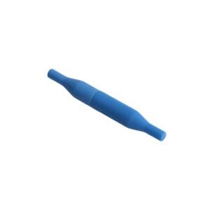
ClickLoc Interconnection Isolation: Connect the miniature coaxial ClickLoc terminal to the extension cable by pushing and turning until the locking detent engages. Insulate the exposed metal body of the coaxial connector union using specialized connector silicone sleeves to prevent accidental paths to chassis ground.
Additional information
Weight
0.6 kg
Dimensions
32 × 16 × 12 mm
0.0
Average Rating
Rated
(0 Reviews)
Rated
0%
Rated
0%
Rated
0%
Rated
0%
Rated
0%
Be the first to review “Bently Nevada 330103-00-06-10-02-CN 3300 XL 8mm Proximity Probe” Cancel reply


0.0 Average Rating Rated (0 Reviews)