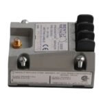
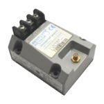
The Bently Nevada 330100-90-00, also cataloged as the 330100 Proximitor Sensor, operates as a dedicated hardware component for physical proximity signal conditioning within 3300 Proximity Transducer System networks. The unit generates a high-frequency radio frequency (RF) excitation signal routed directly to an external probe tip, reads the modulated return parameter caused by target proximity, and provides an analog output voltage directly proportional to the gap distance. By converting raw electromagnetic variations into structured signal fields, the hardware enables immediate static or dynamic processing across the monitor rack backplane.
Suffix Breakdown & Model Matrix
330100: Core hardware platform identifier for the standard 3300 Proximitor Sensor series.
90: Total Length Compatibility Option designating calibration tuning tailored for a 9.0 meter (29.5 feet) overall loop setup.
00: Agency Approval Option specifying that standard industrial execution is deployed without specialized hazardous area certifications.
Hardware Specifications
Parameter
Specification
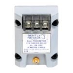
Model
330100-90-00
Brand
Bently Nevada
Origin
USA
Weight
0.29 kg
Dimensions
81.3 mm x 61.2 mm x 103.6 mm
Operating Temp
-35 deg C to +85 deg C
Power Consumption
Requires -17.5 VDC to -26 VDC excitation voltage at 12 mA maximum current draw
System Linearity
7.87 V/mm (200 mV/mil) nominal scale factor deviation across a 2.0 mm linear sweep
Frequency Response
0 to 6.5 kHz bandwidth (+0, -3 dB down limits)
Output Impedance
50 ohms typical raw signal line matching
Base Construction
Cast A383 aluminum casing bonded to an integral electrical isolation plate
Eddy-Current Probe Scaling and Gap Voltage Validation
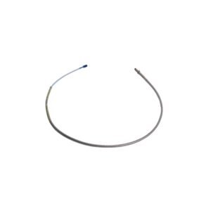
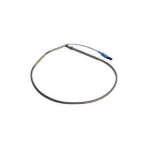
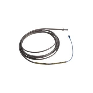
The module demands precise matching of system length variables to enforce a stable eddy-current probe scaling performance profile. This 9.0 meter variant integrates specific internal tank circuits configured to offset the specific resistance and capacitance values of a 9.0 meter hardware combination, such as a 1.0 meter probe joined to an 8.0 meter extension cable. During system setup, field technicians reference the conditioned output loop to verify gap voltage validation against standard -10 VDC targets. This voltage establishes the mechanical center point of the sensing path, minimizing cross-talk suppression failures and keeping the system response fully linear. This calibration prevents signal clip anomalies when the transducer encounters severe rotor dynamics or asymmetric shaft trajectories.
Frequently Asked Questions
Q: Can the field wiring connections or the transducer terminal blocks be altered while the Proximitor sensor is actively receiving supply power?
A: Terminal block disconnection under active supply power will not destroy the internal circuitry. However, severing the connection instantly drops the loop output to near-zero or positive saturation limits, triggering an immediate NOT OK fault state on the companion 3500 series rack and potentially engaging automatic protection interlocks.
Q: How does operating the hardware at an input excitation voltage more positive than -23.5 VDC alter performance?
A: Operating the sensor at supply levels more positive than -23.5 VDC degrades the maximum linear range capability of the loop. While the scale factor remains stable inside tight gaps, the upper boundary of the 2.0 mm sweep suffers clipping because the output amplifier runs out of electrical headroom.
Field Installation Guidelines
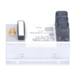
Base Isolation Integrity: Mount the sensor casing using the four integrated mounting holes on the non-conductive base plate. Ensure the physical installation keeps the aluminum housing electrically isolated from structural steel frameworks or machine walls to prevent noise injection from stray ground loops.
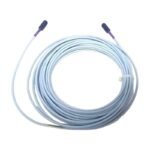
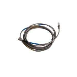
Coaxial Lead Termination: Mate the 9.0 meter tuned probe/cable extension line into the dedicated coaxial input port via the gold-plated ClickLoc connector. Hand-tighten until the collar clicks into place, or implement precise torque loading to a maximum limit of 0.565 N-m (5.0 in-lb).
Terminal Screws Torque Target: Strip field wiring lines back by 7 mm before insertion into the power and signal terminal strip. Torque the binding screws to a maximum of 0.56 N-m (5.0 in-lb) to maintain solid structural wire retention without damaging the terminal threads.
Conduit and Routing Clearances: Route the raw analog output lines inside dedicated metal conduit or grounded cable tracks. Maintain a minimum physical spacing clearance of 152 mm (6.0 inches) from parallel high-voltage AC electric motor cables to eliminate electromagnetic cross-talk.
Additional information
Weight
0.7 kg
Dimensions
26 × 16 × 12 mm
0.0
Average Rating
Rated
(0 Reviews)
Rated
0%
Rated
0%
Rated
0%
Rated
0%
Rated
0%
Be the first to review “Bently Nevada 330100-90-00 3300 Proximitor Sensor” Cancel reply


0.0 Average Rating Rated (0 Reviews)