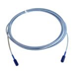
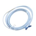
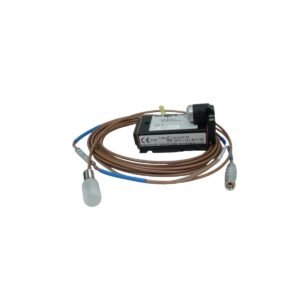
The Bently Nevada 330103-00-07-10-02-00 serves as the primary 330103 Proximity Probe utilized to execute non-contacting shaft displacement and dynamic vibration measurements across 3300 XL 8mm Proximity Transducer platforms. By operating on eddy-current emission principles, the hardware measures static distance variations relative to moving surfaces. The physical probe head tracks high-frequency changes and transmits raw voltage modulations through its integral cable toward an intermediate extension cable, linking the sensor array directly into the machinery protection rack.
Suffix Breakdown & Model Matrix
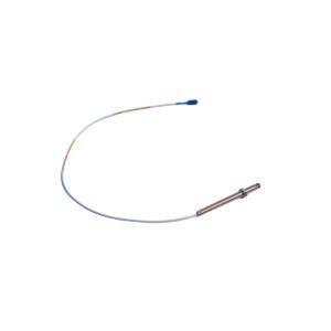
330103: Core model designation for the 3300 XL 8mm Proximity Probe thread profile (M10 x 1 metric housing, unarmored).
00: Unthreaded Length Option specifying 0 mm of unthreaded body layout.
07: Overall Case Length Option defining a total mechanical case dimension of 70 mm.
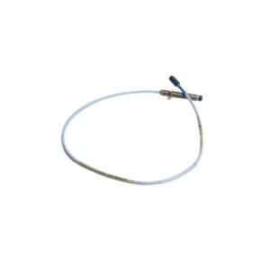
10: Total Length Option indicating a 1.0 meter (3.3 feet) integrated cable assembly.
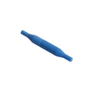
02: Connector Option specifying a miniature coaxial ClickLoc connector structure without a connector protector.
00: Agency Approval Option designating no hazardous area regulatory certificates required for physical deployment.
Hardware Specifications
Parameter
Specification
Model
330103-00-07-10-02-00
Brand
Bently Nevada
Origin
USA
Weight
0.14 kg
Dimensions
70 mm case length, 1.0 m overall cable length
Operating Temp
-52 deg C to +177 deg C
Power Consumption
Passive sensor element (Driven by Proximitor external excitation)
Tip Diameter
8.0 mm
Mounting Thread
M10 x 1 metric thread profile
Core Resistance
7.30 ohms nominal center conductor baseline
Eddy-Current Probe Scaling and Gap Voltage Validation
The physical metrics of the M10 probe tip are balanced to deliver a linear eddy-current probe scaling factor of 7.87 V/mm (200 mV/mil) when targets match AISI 4140 steel. During field installation, mechanical positioning acts as the primary step to execute gap voltage validation, adjusting the probe depth until the signal output matches the standard -10 VDC targets. This specific voltage calibration point centers the sensor inside its 2.0 mm operational range. Maintaining this exact mechanical offset minimizes multi-channel cross-talk and ensures the signal preserves linearity when processing severe rotor dynamics, such as asymmetric shaft orbit shifts and high-speed oil whirl phenomena.
Frequently Asked Questions
Q: Can the 1.0 meter integral cable connector be disconnected or uncoupled while the machine monitor channels remain energized?
A: Yes, physical uncoupling of the ClickLoc terminal can occur while the rack is live. However, breaking the coaxial connection instantly opens the electrical loop, causing the Proximitor sensor output to clamp near its supply limit and triggering a NOT OK fault warning on the protective monitor.
Q: How does selecting the 1.0 meter total probe length configuration restrict the choice of field extension cabling?
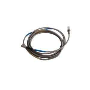
A: The transducer system mandates a matched total electrical length of either 5.0 meters or 9.0 meters. Consequently, this 1.0 meter probe variant requires pairing with a 4.0 meter extension cable for a 5.0 meter loop, or an 8.0 meter extension cable for a 9.0 meter system loop to prevent scale factor derivation drift.
Field Installation Guidelines
Thread Insertion and Torque Limits: Thread the M10 x 1 probe body into the internal machine bracket by hand to prevent thread galling. Use a calibrated torque wrench to tighten the locking hardware to a maximum structural limit of 6.8 N-m (60 in-lb).
Coaxial Connector Cleaning Protocols: Clean the gold-plated elements of the ClickLoc coaxial jack with a fast-evaporating, zero-residue technical contact cleaner prior to final physical mating. Do not allow oil film or moisture to deposit on the internal insulator face.
Minimum Cable Bend Boundaries: Route the 1.0 meter flexible cable leads along the machine frame while ensuring a minimum structural bending radius of 25.4 mm (1.0 inch). Sharp kinks alter the local capacitance properties, which introduces measurement noise.
Isolation and Bracket Routing: Run the sensor lines through dedicated, oil-tight conduits or internal machine passages. Isolate these low-voltage lines from nearby AC motor terminal lines to completely block high-frequency electromagnetic interference from distorting the dynamic signals.
Additional information
Weight
0.8 kg
Dimensions
32 × 36 × 12 mm
0.0
Average Rating
Rated
(0 Reviews)
Rated
0%
Rated
0%
Rated
0%
Rated
0%
Rated
0%
Be the first to review “Bently Nevada 330103-00-07-10-02-00 3300 XL 8mm Proximity Probe” Cancel reply


0.0 Average Rating Rated (0 Reviews)