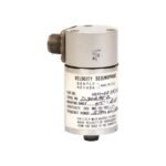
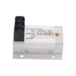
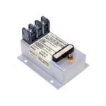
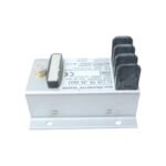
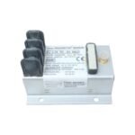
The Bently Nevada 18745-02 operates as a high-precision non-contacting Proximitor sensor built for the legacy 7200 Series Transducer System. This robust hardware component conditions raw high-frequency signals received from 5mm or 8mm eddy-current proximity probes. Consequently, it converts the physical gap distance between the probe tip and the target shaft into a highly stable linear DC voltage signal. By delivering continuous, real-time feedback, the sensor allows machinery protection systems to track shaft vibration, axial position, and radial displacement on critical industrial assets like turbomachinery, compressors, and high-speed pumps.
Hardware Specifications
Parameter
Specification
Model
18745-02
Brand
Bently Nevada
Origin
United States
Weight
Approx. 0.23 kg (0.50 lbs)
Dimensions
10.2 cm x 11.4 cm x 13.2 cm (4.02 in x 4.49 in x 5.20 in)
Operating Temp
-51°C to +100°C (-60°F to +212°F)
Power Consumption
18 to 24 VDC Nominal Input
Scale Factor
200 mV/mil (7.87 V/mm)
Frequency Response
0 Hz (DC) to 10 kHz
System Length
Calibrated for 9-metre (29.5 feet) total electrical system length
Eddy-Current Probe Scaling and Gap Voltage Validation
The internal analog circuitry of the 18745-02 strictly manages eddy-current probe scaling to translate physical gap displacement into a precise linear scale factor of 200 mV/mil. Because improper installation directly induces signal calibration errors, field technicians must execute a meticulous gap voltage validation sequence before securing the monitoring loop. Manually adjusting the probe’s mechanical depth until the sensor output reaches the standard -10 VDC targets verifies that the system operates exactly at the center of its linear calibration curve. Maintaining this sweet spot guarantees that the sensor can capture dynamic rotor dynamics without risking wave clipping during intense, high-amplitude vibration excursions. Furthermore, the robust metal enclosure and integrated terminal separation provide high cross-talk suppression. This layout actively blocks electromagnetic interference from blending across adjacent multi-probe installations mounted within the same termination panel.
Frequently Asked Questions
Q: Can field technicians hot-swap the 18745-02 Proximitor sensor while the monitoring system carries live power?
A: No, you should not hot-swap this sensor while the input power line is fully energized. Unplugging the terminal block under active electrical load can generate transient voltage spikes that damage the sensitive internal oscillator and amplifier modules. Therefore, you must isolate the -24 VDC power supply circuit before replacing the hardware unit.
Q: Why does this specific 18745-02 sensor model specify a 9-metre electrical length restriction?
A: The internal tuning loop requires a fixed total electrical length—combining the physical probe lead and the extension cable—to match exactly 9 metres. If you mismatch these cable lengths, the system will alter its resonant frequency. As a result, the hardware changes its 200 mV/mil scale factor and invalidates your calibrated vibration data readings.
Field Installation Guidelines
Perform Mechanical Gap Calibration: Use a digital multimeter to measure the output terminals continuously during setup. Thread the proximity probe downward toward the target shaft until your voltage reading stabilizes on the precise -10 VDC target baseline.
Isolate Coaxial Connectors: Wrap the connection point between the probe lead and the extension cable with self-fusing insulating tape. This protective barrier stops the metal connector from touching the machine chassis, thereby preventing ground loop interference from skewing measurements.
Enforce Single-Point Shielding: Connect the braided cable shield exclusively to the dedicated instrument ground terminal at the 18745-02 housing side. Concurrently, isolate the outer shield at the machine casing side to guarantee robust cross-talk suppression and eliminate stray currents.
Adhere to Minimum Bend Radii: Route all coaxial extension lines smoothly from the sensor terminal blocks through protective conduits. Avoid crimping or bending the cables past their minimum allowable radius to ensure the high-frequency impedance remains completely stable over time.
Additional information
Weight
0.89 kg
Dimensions
42 × 46 × 49 mm
0.0
Average Rating
Rated
(0 Reviews)
Rated
0%
Rated
0%
Rated
0%
Rated
0%
Rated
0%
Be the first to review “Bently Nevada 18745-02 7200 Series Proximitor Sensor” Cancel reply


0.0 Average Rating Rated (0 Reviews)