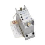
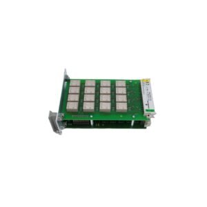
Bently Nevada 1800/20-XX-90-02-00 dual vibration monitor. Brand New, Original Stock, Global Shipping available for automated plant asset safety networks.
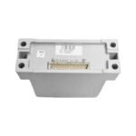
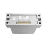
The Bently Nevada 1800/20-XX-90-02-00 serves as the primary 1800/20 Dual Vibration Monitor utilized to execute continuous mechanical asset protection and vibration tracking across industrial motor, pump, fan, and small compressor platforms. This rail-mounted component accepts raw electrical inputs from up to two independent acceleration, velocity, or proximity transducers. The internal processor converts these high-frequency physical signals into isolated, linear 4-20 mA analog outputs while monitoring programmable alarm setpoints to trigger onboard hardware relays for automated machine protection.
Suffix Breakdown & Model Matrix
The alphanumeric matrix configuration defines the specific factory calibration configurations, sensor input matching parameters, and regional certification structures for the device assembly.
1800/20: 1800 Series Dual Vibration Monitor base designator featuring dual-channel processing architecture.
XX: Transducer Input Option (Variable option code specifying the exact sensor hardware match, such as 3300 XL proximity probes, accelerometers, or velocity sensors).
90: Mounting Option (Equipped with an integrated high-stability 35 mm DIN rail mounting clip assembly).
02: Relay Option (Configured with two independent, programmable solid-state SPDT machinery protection relays).
00: Agency Approval Option (Indicates standard uncertified/non-hazardous area production parameters).
Hardware Specifications
Parameter
Specification
Model
1800/20-XX-90-02-00
Brand
Bently Nevada
Origin
United States
Weight
0.36 kg
Dimensions
120 mm x 100 mm x 60 mm
Operating Temp
-40 to +85 deg C
Power Consumption
Less than 6 W at nominal electrical load
Supply Voltage
24 VDC nominal (22 to 30 VDC allowable input range)
To preserve calibrated precision across dynamic machinery components, the configurable transducer processing core must map raw signal variances to actual shaft lateral tracking. When the variable XX option is configured for eddy-current proximity probes, field technicians perform precise gap voltage validation during loop alignment. They adjust the physical probe position until the quiescent signal registers the specific -10 VDC targets required to locate the measurement in the center of the probe linear range.
This mechanical alignment enables the monitor to detect subtle shifts in the machinery rotor dynamics profile, including unbalance, misalignment, or sub-synchronous oil whirl. Additionally, the electronic architecture enforces high cross-talk suppression between parallel measurement circuits running through standard plant conduit layouts.
Frequently Asked Questions
Q: How does the monitor execute fail-safe protection during a total transducer circuit failure?
A: The monitor forces its internal OK relay to de-energize and drops the corresponding channel current loop output below 3.6 mA within microseconds of detecting an open or short circuit. This action suppresses false vibration trips while alerting the host control network of a sensor fault.
Q: What is the mechanical switching latency of the integrated solid-state protection relays?
A: The onboard protection relays feature a hardware response latency of less than 30 milliseconds from the exact moment an input signal crosses a programmed alarm threshold, facilitating rapid emergency machinery shutdown.
Field Installation Guidelines
Secure DIN Rail Attachment: Snap the monitor housing vertically onto a standard 35 mm DIN rail. Ensure the upper and lower integrated mechanical locking tabs engage fully to prevent loose component connections in environments subject to high-frequency industrial vibration.
Enforce Terminal Connection Torque Limits: Tighten all power, signal, and relay interface screw connections to a maximum torque setting of 0.56 N m (5 in lb). Exceeding this ceiling strips the physical wire-clamping hardware inside the block.
Apply Coaxial Shield Grounding Topologies: Terminate the incoming cable shield wire exclusively at the dedicated shield common terminal of the monitor frame. Do not ground the cable shield at both structural boundaries to eliminate ground loop currents.
Isolate Signal Conduit Paths: Route all transducer field wiring inside dedicated, grounded steel conduits. Maintain a minimum physical separation distance of 150 mm (6.0 inches) from high-voltage AC cables and variable frequency drive (VFD) output lines.
Additional information
Weight
0.8 kg
Dimensions
32 × 16 × 12 mm
0.0
Average Rating
Rated
(0 Reviews)
Rated
0%
Rated
0%
Rated
0%
Rated
0%
Rated
0%
Be the first to review “Bently Nevada 1800/20-XX-90-02-00 1800 Series Dual Vibration Monitor” Cancel reply


0.0 Average Rating Rated (0 Reviews)