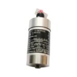
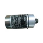
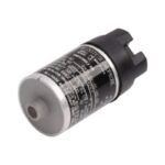
Configured for mechanical machinery monitoring in turbine supervisory instrumentation (TSI) platforms, the Bently Nevada 9200-03-06-10-00 (9200 Velocity Transducer) provides direct physical/electrical execution. This self-generating, two-wire hardware component tracks absolute structural displacement by capturing bearing housing and machinery casing vibration data. The moving-coil internal architecture translates mechanical casing velocity into a continuous proportional voltage signal, routing real-time machinery health data to external 3500 series protection networks or portable analytic diagnostics equipment without utilizing external excitation power.
Suffix Breakdown & Model Matrix
The unique alphanumeric matrix configuration defines the exact physical mounting layout, orientation tuning, internal structural elements, and regulatory compliance parameters for this specific sensor hardware.
9200: Seismoprobe Velocity Transducer base model series designator incorporating internal moving-coil tracking mechanics.
03: Transducer Mounting Angle Option (Specifies a 90 deg +/-2.5 deg vertical mounting orientation tuned for a 4.5 Hz minimum operating frequency).
06: Connector Option (Equipped with a top-mounted coaxial connector interface designed primarily for test equipment connectivity).
10: Mounting Base Option (Features a rigid circular structural base utilizing a metric M10 x 1 standard mounting stud configuration).
00: Agency Approval Option (Indicates production under standard commercial guidelines with no specialized regional hazardous area certifications).
Hardware Specifications
Parameter
Specification
Model
9200-03-06-10-00
Brand
Bently Nevada
Origin
United States
Weight
0.30 kg
Dimensions
41 mm diameter x 102 mm height
Operating Temp
-29 to +121 deg C
Power Consumption
Passive, self-generating device (0 mA current draw from monitor)
Electrical Sensitivity
20 mV/mm/s (500 mV/in/s) at +22 deg C and 100 Hz
Frequency Response
4.5 Hz to 1,000 Hz (+0 dB, -3 dB typical attenuation envelope)
Dynamic Range
2.54 mm peak-to-peak maximum physical displacement
Internal Coil Resistance
1.25 kOhm +/-5% internal tolerance window
Shock Resistance
Withstands 50 g peak maximum acceleration on non-sensitive axis
Transverse Sensitivity
Maximum limit of +/-10% relative to the primary sensitive axis
Eddy-Current Probe Scaling and Rotor Dynamics
To preserve calibrated execution across low-frequency tracking fields, the internal magnetic core requires precise orientation matching to maintain a calibrated mechanical balance. Consequently, this specialized 90 deg configuration works to isolate structural noise by providing strict cross-talk suppression against horizontal wave transmission.
While eddy-current probe scaling tracks relative shaft motion via external Proximitor gap voltage validation, this Seismoprobe sensor tracks absolute casing motion by generating an electromagnetic current as the internal coil cuts across permanent internal magnetic paths. This independent physical measurement provides full structural alignment tracking, allowing plant operators to cross-reference absolute bearing housing vibration with rotor dynamics data to evaluate casing transmission losses or foundation structural elasticity.
Frequently Asked Questions
Q: Why does the 9200-03-06-10-00 model require a specific 90 degree mounting orientation during field deployment?
A: The moving-coil spring assembly inside this version requires vertical gravity alignment to function within its linear envelope. Mounting this sensor horizontally shifts the internal core, causing the coil to bind against the permanent magnets and distorting the voltage output.
Q: Can this velocity transducer connect directly to an unisolated low-impedance input loop?
A: No, this hardware requires termination into a minimum 10 kOhm load impedance. Lower electrical loads damp the moving-coil assembly, altering the 20 mV/mm/s sensitivity scale factor and dropping the low-frequency response ceiling.
Field Installation Guidelines
Enforce Mounting Base Torque Constraints: Anchor the metric M10 x 1 mounting stud into the machine casing tap using a calibrated torque wrench. Tighten the interface to exactly 5.6 N m (50 in lb) to ensure uniform mechanical signal transmission without stripping threads.
Observe Single-Point Grounding Rules: Terminate the coaxial outer shield layer exclusively at the common node of the receiver instrumentation card. Do not earth the cable shield at the machine casing to avoid structural ground loop noise insertion.
Verify Surface Contact Planarity: Ensure that the machined flat face on the machinery bearing housing matches or exceeds the 41 mm circular diameter of the sensor base. Surface irregularities prevent linear high-frequency energy transfer.
Implement Mechanical Strain Relief: Anchor the interconnecting coaxial cable to a rigid support point within 150 mm (6.0 inches) of the top-mount connector housing to isolate the interface pins from pulling forces and dynamic cable fatigue.
Additional information
Weight
1 kg
Dimensions
26 × 16 × 28 mm
0.0
Average Rating
Rated
(0 Reviews)
Rated
0%
Rated
0%
Rated
0%
Rated
0%
Rated
0%
Be the first to review “Bently Nevada 9200-03-06-10-00 Seismoprobe Velocity Transducer” Cancel reply


0.0 Average Rating Rated (0 Reviews)