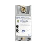
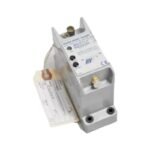
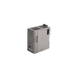
Configured for machinery safety protection in plant asset monitoring networks, the Bently Nevada 1800/20-12-90-02-00 (1800/20 Dual Vibration Monitor) provides direct physical/electrical execution. This standalone, rail-mountable electronic module acts as a continuous machine protection device that monitors two independent channels of absolute casing vibration or relative structural displacement. The hardware captures raw transducer data, evaluates user-defined alarm thresholds, and drives onboard solid-state relays to trigger automated trip signals, eliminating the need for a centralized rack assembly.
Hardware Specifications
Parameter
Specification
Model
1800/20-12-90-02-00
Brand
Bently Nevada
Origin
United States
Weight
0.35 kg
Dimensions
120 mm x 100 mm x 60 mm
Operating Temp
-40 to +85 deg C
Power Consumption
Less than 6 W at nominal load
Supply Voltage
24 VDC nominal (+/-10% input tolerance window)
Inputs
2 independent channels (Proximity or Accelerometer)
To preserve measurement integrity across complex structural vibration spectra, the monitor features configurable scale factor processing capable of mapping a standard 7.87 V/mm (200 mV/mil) proximity probe or a 10.2 mV/m/s2 (100 mV/g) accelerometer input. When utilizing eddy-current sensors, field technicians verify the mechanical alignment via real-time gap voltage validation. They monitor the sensor output to ensure it matches the specific -10 VDC targets required to anchor the measurement in the center of the probe’s linear operational window.
This accurate physical alignment allows the dual-channel processor to evaluate changes in machine rotor dynamics profiles without signal distortion. Furthermore, internal electronic filtering circuits enforce cross-talk suppression between adjacent measurement paths, preventing high-frequency noise from parallel sensor lines from triggering false threshold alarms.
Frequently Asked Questions
Q: What is the maximum switching delay for the onboard protection relays during a high-vibration trip event?
A: The solid-state output relays feature an internal response latency of less than 30 milliseconds from the moment a signal violates the programmed alarm limits, ensuring rapid machinery shutdown execution.
Q: How does the monitor handle a sudden loss of transducer circuit continuity or an internal software fault?
A: The module executes a fail-safe state routine. It de-energizes the system OK relay, drops the corresponding 4-20 mA output loop current below 3.6 mA, and inhibits latching vibration relays to prevent erroneous trips caused by broken cables.
Field Installation Guidelines
Ensure Proper DIN Rail Mounting: Mount the transmitter module vertically on a standard 35 mm DIN rail. Confirm that the upper and lower integrated mechanical locking tabs clip fully onto the rail assembly to withstand high ambient industrial vibration.
Enforce Terminal Connection Torque Constraints: Secure all terminal connections on the terminal block using a maximum torque of 0.56 N m (5 in lb). Exceeding this mechanical ceiling damages the terminal thread frames.
Apply Coaxial Shielding Ground Guidelines: Connect the incoming cable shield wire exclusively to the dedicated shield common terminal on the monitor housing. Do not ground the cable shield at the machine casing or sensor head to prevent ground loops.
Isolate Low-Voltage Signal Lines: Route all sensor field wiring inside grounded steel conduits. Maintain a minimum distance separation of 150 mm (6.0 inches) from all high-voltage AC lines and electrical motor power cables.
Additional information
Weight
0.6 kg
Dimensions
26 × 18 × 12 mm
0.0
Average Rating
Rated
(0 Reviews)
Rated
0%
Rated
0%
Rated
0%
Rated
0%
Rated
0%
Be the first to review “Bently Nevada 1800/20-12-90-02-00 1800 Series Dual Vibration Monitor” Cancel reply


0.0 Average Rating Rated (0 Reviews)