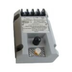
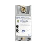
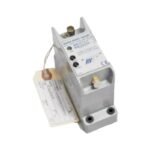
Bently Nevada 1800/15-12-90-02-00 vibration transmitter module. Brand New, Original Stock, Global Shipping available for automated machinery monitoring networks.
The Bently Nevada 1800/15-12-90-02-00 serves as the primary 1800/15 Relative Vibration Transmitter utilized to execute non-contacting shaft displacement and dynamic casing vibration monitoring across industrial pump, fan, and utility compressor platforms. This self-contained, rail-mountable transmitter converts raw high-frequency electrical signals from an external eddy-current proximity probe into an isolated, linear 4-20 mA analog current loop output. By eliminating the necessity for intermediate machinery protection racks, the device streams direct machinery health metrics into distributed control systems and programmable logic controllers.
Hardware Specifications
Parameter
Specification
Model
1800/15-12-90-02-00
Brand
Bently Nevada
Origin
United States
Weight
0.30 kg
Dimensions
120 mm x 80 mm x 60 mm
Operating Temp
-40 to +85 deg C
Power Consumption
Less than 5 W at rated load
Supply Voltage
24 VDC nominal (+/-10% input tolerance window)
Measurement Range
0.1 to 100 mm/s RMS full-scale range
Frequency Response
0.1 Hz to 10,000 Hz (+0 dB, -3 dB attenuation points)
Output Signal
4-20 mA DC analog current loop output
Digital Interface
Modbus RTU protocol over serial connection
Isolation Rating
500 VDC channel-to-frame continuous rating
Eddy-Current Probe Scaling and Rotor Dynamics
To preserve calibrated precision across the 10,000 Hz bandwidth, the internal transmitter processing core maps raw sensor impedances to exact shaft lateral movement. Consequently, field technicians perform precise gap voltage validation during system commissioning, adjusting the underlying transducer probe until the circuit registers the targeted quiescent midpoint. This physical adjustment positions the sensor within its linear performance envelope, allowing the hardware to track structural anomalies in the machinery rotor dynamics profile.
Furthermore, the advanced active conditioning design achieves high cross-talk suppression between parallel signal channels grouped together inside industrial terminal enclosures. This shielding layout minimizes inductive noise coupling from adjacent high-voltage machinery lines.
Frequently Asked Questions
Q: How does the transmitter handle an abrupt hardware failure or open circuit in the external proximity probe cable?
A: The transmitter actively drops its analog output loop current below 3.6 mA within microseconds of detecting a probe fault. This diagnostic signal suppression prevents false high-vibration trips while alerting the host control platform of a sensor failure.
Q: Can this specific transmitter interface simultaneously with Modbus RTU serial links and standard analog receivers?
A: Yes, the module provides concurrent data routing through the isolated 4-20 mA current loop terminal and the serial Modbus network, allowing simultaneous execution of real-time safety shut-down logic and slow-rate trend analysis.
Field Installation Guidelines
Enforce Component Mounting Stability: Mount the enclosure onto a standard 35 mm DIN rail inside a protective, weatherproof junction box. Ensure the locking tabs click fully into position to prevent high-frequency mechanical vibration from loosening the assembly.
Implement Terminal Wire Torque Limits: Tighten all power and signal interface screw connections to a maximum torque setting of 0.56 N m (5 in lb). Exceeding this mechanical ceiling strips the interior physical wire clamping frames.
Establish Shield Grounding Topologies: Ground the outer coaxial shield wire exclusively at the dedicated transmitter common terminal block. Do not ground the cable shield at both structural boundaries to prevent ground loop currents from injecting electrical noise into the signal path.
Observe Distance Separation Parameters: Route all incoming sensor extension lines a minimum distance of 150 mm (6.0 inches) away from electrical motors, high-current AC power cables, and inductive switching actuators.
Additional information
Weight
0.6 kg
Dimensions
36 × 16 × 12 mm
0.0
Average Rating
Rated
(0 Reviews)
Rated
0%
Rated
0%
Rated
0%
Rated
0%
Rated
0%
Be the first to review “Bently Nevada 1800/15-12-90-02-00 1800 Series Relative Vibration Transmitter” Cancel reply


0.0 Average Rating Rated (0 Reviews)