Premium 131151-01 tachometer speed module available. Brand new original stock with immediate global shipping options for industrial monitoring systems.
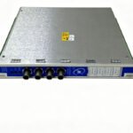
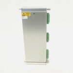
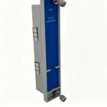
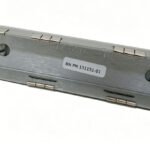
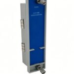
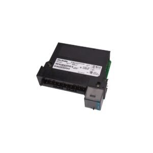
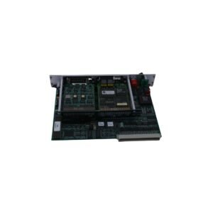
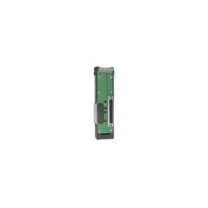
The Bently Nevada 131151-01 serves as the primary 131151-01 Tachometer Module utilized to execute rotational speed measurements and overspeed protection across 3500 Series Machinery Protection System platforms.
Hardware Specifications
Parameter
Specification
Model
131151-01
Brand
Bently Nevada
Origin
United States
Weight
0.85 kg
Dimensions
241.3 mm x 24.4 mm x 163.1 mm
Operating Temp
-30 to +65 deg C
Power Consumption
5.8 W maximum
Signal Inputs
Accepts 2 proximity probe or magnetic pickup signals
Output Signals
4-20 mA DC recorder outputs and buffered transducer outputs
Transducer Supplies
-24 VDC to power proximity sensors
Machinery Monitoring and TSI Characteristics
The 131151-01 processes high-frequency pulses to analyze complex rotor dynamics during critical startup and shutdown sequences. Consequently, field engineers must configure the eddy-current probe scaling to precisely match the gear tooth or keyway geometry, which prevents speed calculation errors. Furthermore, technicians perform routine gap voltage validation to confirm that the input signal maintains a steady bias near the -10 VDC target; as a result, the proximity sensor reliably captures every tooth passing events. Additionally, the microprocessor applies digital cross-talk suppression filters to the input stages, thereby eliminating electromagnetic noise between closely run transducer leads in the cable trays.
Frequently Asked Questions
Q: Does the 131151-01 module allow hot-swapping while the machinery protection system runs?
A: Yes. The hardware design permits hot-swapping under power without disrupting the operations of neighboring modules. However, maintenance personnel must place any associated voting logic or trip relays into bypass mode prior to removal to prevent accidental machine trips.
Q: How does a technician resolve a continuous phase error or erratic speed reading on this specific module?
A: Erratic readings typically stem from improper sensor positioning or magnetic field interference. Therefore, engineers should check the physical gap distance, verify the target wheel condition, and measure the input voltage to ensure it stays within the linear sensor range.
Field Installation Guidelines
Insert the module firmly into the designated chassis slot before tightening the retaining screws, thereby ensuring a secure connection to the 3500 system backplane.
Apply strict shielding protocols to all speed sensor wiring. Specifically, land the outer shield at the 3500 rack ground bar only, while leaving the sensor end ungrounded to isolate the signal loop from local ground potential differences.
Route all pulse input lines away from high-voltage AC motor cables, which reduces inductive noise coupling and ensures clean pulse edge detection.
Additional information
Weight
0.8 kg
Dimensions
40 × 20 × 12 mm
0.0
Average Rating
Rated
(0 Reviews)
Rated
0%
Rated
0%
Rated
0%
Rated
0%
Rated
0%
Be the first to review “Bently Nevada 131151-01 3500/50M Tachometer Module” Cancel reply


0.0 Average Rating Rated (0 Reviews)