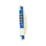
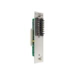
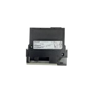
The Bently Nevada 130731-01 is a 3300 series velocity vibration input module. Available Brand New in Original Stock with rapid Global Shipping options.
The Bently Nevada 130731-01, also cataloged as the 130731-01 Velomitor Transducer Input/Output Module, operates as a dedicated hardware component for casing vibration data acquisition within 3300 Machinery Protection System networks. It interfaces directly with piezoelectric velocity sensors, conditioning alternating current (AC) voltage waveforms into continuous absolute vibration signals suitable for safety monitoring across host processing cards.
Hardware Specifications
Parameter
Specification
Model
130731-01
Brand
Bently Nevada
Origin
USA
Weight
0.35 kg
Dimensions
24.2 x 3.0 x 2.5 cm
Operating Temp
-20 to +65 deg C
Power Consumption
1.8 W nominal
Transducer Target
Velomitor / Piezoelectric Accelerometer
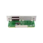
Backplane Printed Wiring Board
PWA 129966-02A
Isolation
500 VRMS galvanic isolation
Machinery Monitoring and TSI Integration
The 130731-01 I/O module transfers low-amplitude high-frequency signals without injecting electronic hum into adjacent Turbomachinery Instrumentation (TSI) racks. Specifically, the onboard instrumentation amplifier matches the impedance requirements of internal solid-state piezoelectric sensors. Consequently, this tight match minimizes signal attenuation over extended field wiring lengths.
Furthermore, the electronic design isolates individual channel input loops to maintain superior cross-talk suppression. As a result, neighboring eddy-current probe scaling functions or deep gap voltage validation procedures (-10 VDC targets) do not distort the velocity calculations. The module acts as a stable buffer stage. Accordingly, it updates the primary rack bus with noise-filtered absolute vibration metrics during extreme rotor dynamics events.
Frequently Asked Questions
Q: How does the 130731-01 hardware handle a broken field sensor line or short circuit condition?
A: The module constantly samples the bias voltage. Subsequently, if a transducer line drops below or exceeds nominal limits, the internal logic flags a sensor fault state and locks out the associated trip relay to prevent false alarms.
Q: Can this specific 130731-01 board be utilized directly within newer 3500 series racks?
A: No. This hardware features physical form factor constraints and pin layouts built exclusively for the 3300 series backplane bus architecture. Therefore, it cannot cross-mount into 3500 platform configurations.
Field Installation Guidelines
Power down the designated 3300 monitoring chassis quadrant before installing or swapping the physical interface board.
Slide the 130731-01 printed wiring assembly along the guide channels until the rear pin header meshes fully into the backplane socket.
Tighten the rear assembly locking screws to 0.5 N-m. Thereafter, check that the metal faceplate makes clean structural contact with the chassis framework.
Route the twisted-pair shielded transducer field cable through isolated low-voltage signal trays. In doing so, maintain at least 30 cm clearance from high-power AC lines to stop inductive coupling.
Secure the field shield drain wires to the main chassis instrument ground terminal block. Finally, activate the power supply to run automated loop check validations.
Additional information
Weight
0.66 kg
Dimensions
33 × 53 × 73 mm
0.0
Average Rating
Rated
(0 Reviews)
Rated
0%
Rated
0%
Rated
0%
Rated
0%
Rated
0%
Be the first to review “Bently Nevada 130731-01 3300 Series Velomitor Transducer I/O Module” Cancel reply


0.0 Average Rating Rated (0 Reviews)