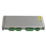
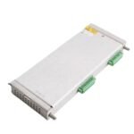
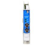
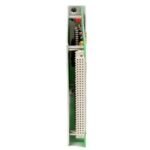
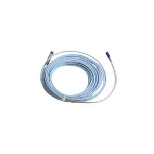
Configured for raw sensor signal conditioning in 3500 Series Machinery Protection System platforms, the Bently Nevada 124534-01 (124534-01 Proximity Transducer Interface Module) provides direct physical/electrical execution.
Hardware Specifications
Parameter
Specification
Model
124534-01
Brand
Bently Nevada
Origin
United States
Weight
0.34 kg
Dimensions
24.1 mm x 244.0 mm x 163.1 mm
Operating Temp
-30 deg C to +65 deg C
Power Consumption
4.5 W maximum
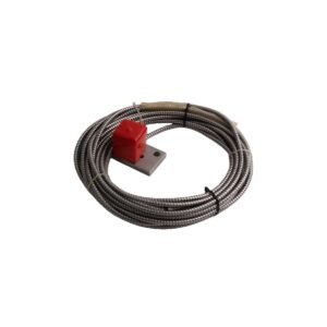
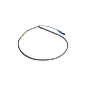
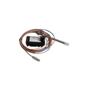
Input Signal
Proximity probe eddy-current sensor input
Output Signal
Conditioned voltage output proportional to gap
Machinery Monitoring & TSI Characteristics
This hardware tracks precise calibration metrics for eddy-current probe scaling across standard 3300 XL 8 mm proximity transducer systems. Specifically, internal circuitry executes continuous gap voltage validation targeting nominal -10 VDC targets. Consequently, this tracking ensures that the sensor operates exclusively within the linear range of the calibration curve. Furthermore, active cross-talk suppression filters isolate adjacent channel frequencies, thereby eliminating mutual inductance noise on high-density machine trains while preserving the absolute integrity of phase trigger and rotor dynamics measurements.
Frequently Asked Questions
Q: How does the system verify the gap voltage validation during field commissioning?
A: Technicians verify the level by connecting a digital multimeter directly to the front-panel buffered output coaxial connectors. Consequently, any DC bias reading outside the -9.5 VDC to -10.5 VDC window immediately indicates improper probe-to-target clearance or physical probe damage.
Q: Does the module backplane design permit hot-swap installation while the rack remains powered?
A: Yes, because the internal architecture incorporates dedicated power-limiting circuit traces, operators can safely extract or insert the module without disrupting the main system power bus or altering the behavior of adjacent active channels.
Field Installation Guidelines
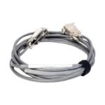
Shielding Termination: First, strip the outer jacket of the transducer extension cable. Following this step, terminate the braided shield exclusively at the system instrument ground bus bar. Do not ground the shield at the field sensor housing, as this layout creates ground loops.
Chassis Grounding: Secure the module faceplate screws using a calibrated torque wrench set to 0.7 N-m. As a result, this process establishes mechanical and electrical continuity between the module frame and the grounded 19-inch rack enclosure.
Terminal Routing: Route low-voltage proximity sensor input wires through independent channels. Meanwhile, maintain a minimum physical clearance of 50 mm from any high-voltage AC power distribution or motor control cables within the conduit system.
Additional information
Weight
0.6 kg
Dimensions
26 × 20 × 20 mm
0.0
Average Rating
Rated
(0 Reviews)
Rated
0%
Rated
0%
Rated
0%
Rated
0%
Rated
0%
Be the first to review “Bently Nevada 124534-01 Proximity Transducers Interface Module” Cancel reply


0.0 Average Rating Rated (0 Reviews)