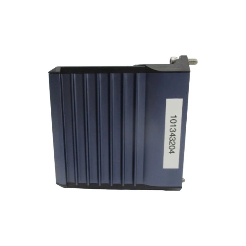
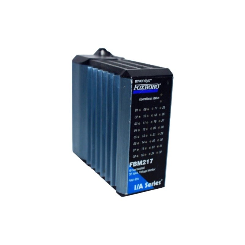
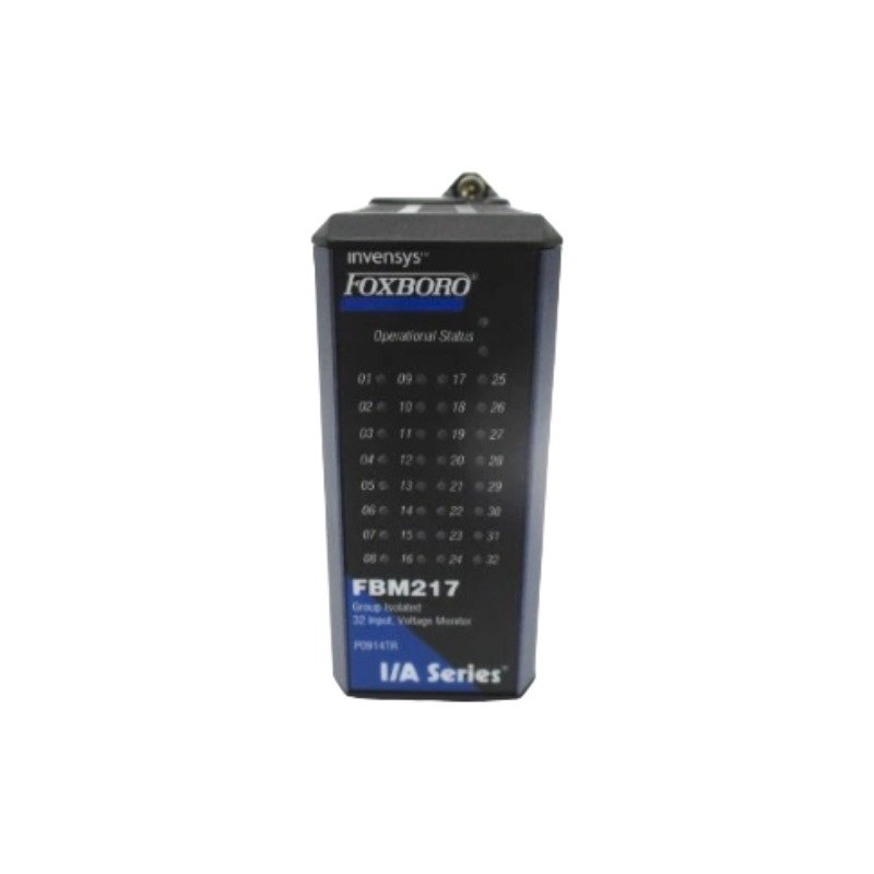
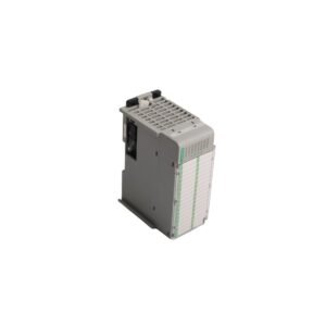
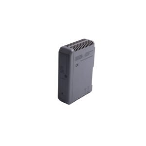
The Foxboro FBM217 P0914TR, also cataloged as the FBM217 Group Isolated Input Module, operates as a dedicated hardware component for discrete/analog group isolation and signal conversion within Foxboro I/A Series DCS platforms.
Hardware Specifications
Parameter
Specification
Model
FBM217 P0914TR
Brand
Foxboro
Origin
USA
Weight
2 kg
Dimensions
100 mm x 50 mm x 30 mm
Operating Temp
-20 to +70 deg C
Power Consumption
24 VDC redundant input bus powered
Input Voltage
24 VDC
Output Signal Range
4-20 mA
Communication Interface
RS485
Isolation Type
Group isolated input channels
Process Control Integration and Signal Isolation
Configured for high-density panel integration, the FBM217 P0914TR conditions incoming field loops by converting 24 VDC input signals into standardized 4-20 mA outputs. Embedded galvanic barriers provide group isolation across channels, suppressing differential ground potentials between field instruments and backplane logic units. When interfaced with field transmitters running 4-20 mA HART loop protocol configurations over RS485 communication channels, internal filtering maintains steady analog-to-digital conversions. For high-density sensor points wired through local termination blocks, cold junction compensation (CJC) maintains calibrated measurement baselines during thermal ambient shifts.
Frequently Asked Questions
Q: How does the group isolation design on the FBM217 P0914TR handle ground potential shifts?
A: Internal galvanic barriers isolate field input groups from the central system backplane. This isolation prevents ground loops and high common-mode voltages from damaging backplane communication circuitry or corrupting neighboring channel readings.
Q: What procedures apply to hot-swapping the FBM217 P0914TR in an active DCS baseplate?
A: Technicians can insert or remove the module without de-energizing the baseplate power bus. However, operators must observe standard electrostatic discharge (ESD) handling protocols to prevent damage to baseplate pin connectors during hot insertion.
Field Installation Guidelines
Align the FBM217 P0914TR module with the designated baseplate slot and press firmly until top and bottom latches snap locked.
Terminate 24 VDC power and field input lines at the baseplate terminal assembly, ensuring signal lines use shielded twisted-pair cables.
Ground cable shield drain wires at a single functional instrument earth point within the control cabinet to maintain high signal-to-noise ratios.
Maintain a minimum physical clearance of 200 mm between low-voltage 24 VDC / 4-20 mA signal runs and high-voltage AC distribution wiring inside enclosure wire ducts.
Additional information
Weight
2.00 kg
Dimensions
67 × 45 × 75 mm
0.0
Average Rating
Rated
(0 Reviews)
Rated
0%
Rated
0%
Rated
0%
Rated
0%
Rated
0%
Be the first to review “Foxboro FBM217 P0914TR Group Isolated Input Module” Cancel reply











0.0 Average Rating Rated (0 Reviews)