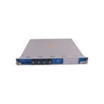
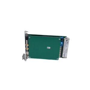
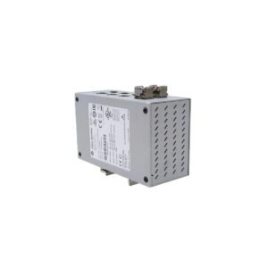
Bently Nevada P3403893-0351 is a 2-wire 4-20 mA loop-powered vibration transmitter with non-interacting zero and span controls. Brand New, Original Stock with Global Shipping.
The Bently Nevada P3403893-0351, also cataloged as the P3403893-0351 Vibration Transmitter, operates as a dedicated hardware component for continuous machinery case and structural vibration tracking within machinery health platforms. This loop-powered, two-wire device conditions raw high-frequency waveforms from non-contacting proximity probes and maps the results into a linear analog signal directly proportional to peak-to-peak vibration parameters.
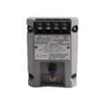
The internal transmitter circuitry interfaces with a single non-contacting proximity sensor, maintaining tight eddy-current probe scaling configurations without requiring an external driver enclosure. The hardware provides continuous gap voltage validation (-10 VDC targets) through unisolated “PROX OUT” and “COM” terminals, ensuring the sensor operates within the 0.5 mm to 1.75 mm linear target boundary. Furthermore, an integrated Not OK / Signal Defeat circuit delivers complete cross-talk suppression and false alarm mitigation, forcing the primary 4-20 mA loop to drop below 3.6 mA within 100 microseconds of a probe or cable connection failure to prevent false trips during transient rotor dynamics.
Frequently Asked Questions
Q: How does the integrated Power-Up Inhibit safety function operate on the P3403893-0351 device?
A: Upon initialization, the internal circuit clamps the loop output current below 3.6 mA for a fixed 2 to 3 second delay. This prevents downstream control platforms from registering false high-vibration spikes during the electrical stabilization of the transmitter.
Q: Can the 4-20 mA loop span and zero limits be field-calibrated after installation?
A: Yes, the module features non-interacting zero and span adjustment potentiometers situated beneath the access seal labels. These allow independent adjustment of the full-scale range endpoints without requiring iterative tuning cycles.
Field Installation Guidelines
Secure the transmitter to the enclosure base panel utilizing standard bulkhead screws or snap the module directly onto a matching symmetrical DIN rail matrix.
Terminate the 2-wire 4-20 mA instrumentation cable to the designated loop supply terminals, ensuring input potential matches the +24 VDC industrial standard.
Keep the unisolated dynamic BNC diagnostic port lead length under 3 meters (10 feet) to prevent severe capacitive signal loss across the test interface.
Establish the field transducer cable shield ground termination exclusively at the transmitter common block, keeping the sensor housing floating to isolate structural ground potential.
Additional information
Weight
0.55 kg
Dimensions
50 × 70 × 60 mm
0.0
Average Rating
Rated
(0 Reviews)
Rated
0%
Rated
0%
Rated
0%
Rated
0%
Rated
0%
Be the first to review “Bently Nevada P3403893-0351 Vibration Transmitter” Cancel reply


0.0 Average Rating Rated (0 Reviews)