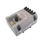
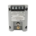
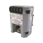
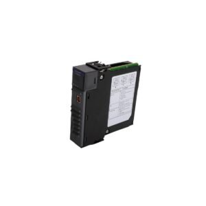
The Bently Nevada 991-25-70-01-01, also cataloged as the 991 Thrust Transmitter, operates as a dedicated hardware component for axial displacement monitoring within machinery protection systems. Configured as a 2-wire, loop-powered device, it converts the physical proximity input from a 3300 NSv proximity transducer system into a standardized proportional 4-20 mA output current loop for PLC or DCS interfaces.
Hardware Specifications
Parameter
Specification
Model
991-25-70-01-01
Brand
Bently Nevada
Origin
United States
Weight
0.43 kg
Dimensions
81.3 mm x 61.2 mm x 50.8 mm
Operating Temp
-35 to +85 deg C
Power Consumption
12 to 35 VDC input range (loop-powered)
Full-Scale Option
25-0-25 mils (0.6-0-0.6 mm) current loop linear range
System Length
7.0 meters (23.0 feet)
Mounting Type
35 mm DIN-rail clips
Agency Approval
CSA Division 2, ATEX Zone 0/Zone 2, ABS maritime
Dynamic Output
PROX OUT coaxial connector, 7.87 mV/micrometer (200 mV/mil)
Proximity Probe Scaling and Rotor Dynamics Calibration
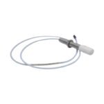
The Bently Nevada 991-25-70-01-01 relies on correct eddy-current probe scaling to ensure accuracy across its full-scale displacement span. Consequently, proper calibration requires strict gap voltage validation, which targets a -10 VDC baseline at the electrical midpoint of the linear window via the integrated PROX OUT dynamic terminal. Furthermore, field variations in target material chemistry modify magnetic permeability and electrical conductivity, shifting the nominal 7.87 mV/micrometer scale factor. To maintain critical rotor dynamics monitoring, engineers must execute cross-talk suppression between adjacent probes by establishing physical separation distances that exceed twice the probe tip diameter, thereby preventing electromagnetic field overlap and subsequent heterodyne interference.
Frequently Asked Questions
Q: How does the transmitter respond if the 3300 NSv proximity probe or extension cable fails?
A: The device incorporates an active Not OK/Signal Defeat circuit. Therefore, when an electrical fault occurs, the internal processor drops the loop signal output to less than 3.6 mA within 100 microseconds, shifting the system safely into a fault-safe monitoring state.
Q: Can AC-powered diagnostic instruments attach directly to the PROX OUT coaxial connector?
A: The PROX OUT terminal shares a common ground that is not isolated from the 4-20 mA current loop. Consequently, users must implement an external test adapter to isolate grounded, AC-powered test equipment and prevent loop corruption.
Field Installation Guidelines
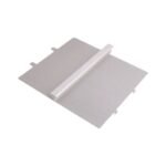
DIN-Rail Assembly: Snap the integrated 35 mm DIN-rail clips securely onto standard symmetrical rail profiles, ensuring that the grounding tab establishes a low-impedance connection with the metal rail infrastructure.
Target Dimensions: Maintain a minimum diameter of 9.5 mm on the target shaft surface directly beneath the probe tip to eliminate edge-effect signal distortion from under-scaled target sizing.
Current Loop Resistance: Verify that total loop resistance, including field wiring and terminal junctions, remains below 1000 ohms when the system operates at the maximum 35 VDC supply limit.
Shield Grounding Execution: Terminate the coaxial extension cable shielding explicitly at the transmitter housing ground block, but keep the instrumentation side floating if the facility designates an external system earth point.
Additional information
Weight
0.43 kg
Dimensions
110 × 80 × 130 mm
0.0
Average Rating
Rated
(0 Reviews)
Rated
0%
Rated
0%
Rated
0%
Rated
0%
Rated
0%
Be the first to review “Bently Nevada 991-25-70-01-01 Thrust Transmitter” Cancel reply


0.0 Average Rating Rated (0 Reviews)