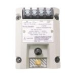
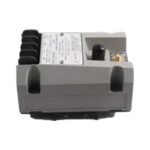
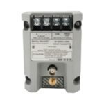
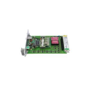
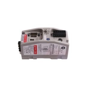
The Bently Nevada 991-06-50-01-01 serves as the primary 991 Thrust Transmitter utilized to execute axial displacement monitoring across machinery monitoring platforms. The hardware accepts raw voltage signals from a non-contacting proximity probe system and converts the linear shaft position changes into a proportional 4-20 mA analog loop output.
Hardware Specifications
Parameter
Specification
Model
991-06-50-01-01
Brand
Bently Nevada
Origin
United States
Weight
0.43 kg
Dimensions
114.3 mm x 63.5 mm x 38.1 mm
Operating Temp
-35 deg C to +85 deg C
Power Consumption
Less than 1.0 W
System Input
3300 NSv Proximity Probe and Extension Cable
Signal Output
4-20 mA DC (proportional to axial movement)
Supply Voltage
12 to 35 VDC
System Length
5.0 meters
Agency Approval
CSA Division 2 certified
Eddy-Current Probe Scaling and Gap Voltage Validation
The hardware incorporates internal eddy-current probe scaling to translate high-frequency electrical fields into precise physical displacement variables. During system setup, field technicians perform gap voltage validation to anchor the calibrated electrical center, tracking the mechanical voltage output until it stabilizes at the -10 VDC baseline target. This alignment prevents false readings induced by complex rotor dynamics under changing thrust loads. Additionally, integrated high-frequency filters provide robust cross-talk suppression, which effectively blocks mutual inductive interference from neighboring eddy-current transducers.
Frequently Asked Questions
Q: What engineering range corresponds to the “06” option code on this transmitter?
A: The “06” option specifies a calibrated full-scale axial displacement range of 30-0-30 mils or 0.75-0-0.75 mm of total thrust travel.
Q: What does the “50” code indicate within the 991-06-50-01-01 model matrix?
A: The “50” option designates a hardware configuration calibrated for a 5.0 meter total system length (combined probe and extension cable matching).
Q: How fast does the Not OK fault circuit respond to a field loop or sensor failure?
A: The integrated fault detection circuit clamps the loop output below 3.6 mA within 100 microseconds of a detected open or short circuit to signal a probe error.
Field Installation Guidelines
Fix the module securely to a grounded 35 mm DIN rail inside an environmental enclosure to shield against industrial contaminants.
Ensure a structural thread engagement length equal to 1.5 times the nominal thread diameter when mounting the primary probe into the machine casing.
Segregate all low-voltage proximity instrumentation wires from high-current power cables and variable-frequency drive lines to prevent EMI noise injection.
Connect the extension cable outer armor to the local junction box bulkhead plate while terminating the 4-20 mA loop shield solely at the receiver ground.
Additional information
Weight
0.43 kg
Dimensions
60 × 36 × 40 mm
0.0
Average Rating
Rated
(0 Reviews)
Rated
0%
Rated
0%
Rated
0%
Rated
0%
Rated
0%
Be the first to review “Bently Nevada 991-06-50-01-01 991 Thrust Transmitter” Cancel reply


0.0 Average Rating Rated (0 Reviews)