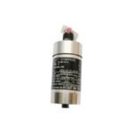
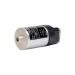
Configured for absolute casing vibration measurements in machinery monitoring networks, the Bently Nevada 9200-06-05-10-00 operates as a moving-coil velocity transducer. Specifically, the self-generating hardware functions without external power excitation and subsequently converts structural or bearing housing vibration velocity into a proportional analog voltage output. Consequently, this design executes the direct delivery of dynamic machinery velocity metrics to machinery protection monitors or diagnostic instruments.
Hardware Specifications
Parameter
Specification
Model
9200-06-05-10-00
Brand
Bently Nevada
Origin
USA
Weight
0.30 kg (10.5 oz) typical
Dimensions
41 mm diameter x 102 mm height
Operating Temp
-29 deg C to +121 deg C
Power Consumption
Self-generating (No external power required)
Sensitivity
20 mV/mm/s (500 mV/in/s) at 100 Hz, ±5%
Frequency Response
4.5 Hz to 1000 Hz (+0, -3 dB typical)
Mounting Orientation
0 deg to 180 deg universal mounting (Omnidirectional orientation)
Connector Configuration
Side mount connector interface (with internal terminal block option)
Mounting Base Thread
M10 x 1.25 metric threaded stud
Transducer Dynamics and Operating Constraints
The Bently Nevada 9200-06-05-10-00 relies on internal moving-coil dynamics rather than eddy-current probe scaling to measure absolute structural velocities. Field setup replaces standard proximity probe gap voltage validation (-10 VDC targets) with mechanical alignment based on the calibrated mounting orientation code. Because this specific configuration utilizes the universal orientation spring package, it can be mounted at any angle from vertical to horizontal without requiring distinct calibration setups. To preserve signal integrity across multi-transducer networks, the heavy anodized aluminum housing provides electromagnetic shielding; as a result, the hardware minimizes signal degradation when field lines route through parallel wireways.
Frequently Asked Questions
Q: What specific layout parameters do the options in the 9200-06-05-10-00 configuration define?
A: The option codes define a 0 to 180 deg universal/omni mounting orientation angle (06), a side-mount terminal block/connector layout configuration (05), an M10 x 1.25 metric mounting base thread (10), and a configuration requiring no specialized agency approvals (00).
Q: Can this self-generating moving-coil transducer drive long field cable distances?
A: Yes. Because the transducer generates a low impedance voltage signal via its internal 1.25 kOhm nominal coil resistance, it can drive shielded instrumentation cables up to significant distances without high-frequency signal attenuation.
Field Installation Guidelines
Shielding and Grounding: First, secure the twisted-pair field wiring to the side-mount connector assembly. Afterward, ground the overall cable shield at a single point inside the instrument panel or monitor rack to prevent ground loop noise from corrupting the dynamic velocity wave signal.
Conduit and Routing Rules: Always route transducer output cables inside dedicated, grounded metal conduits. In addition, avoid running signal conductors parallel to high-voltage AC lines or variable frequency drive (VFD) motor cables to suppress electromagnetic noise.
Mechanical Mounting: Torquing forces affect sensor performance; therefore, tighten the M10 x 1.25 threaded mounting stud to exactly 5.6 N-m (50 in-lb) using a calibrated torque wrench. Ensure the mounting surface is clean, flat, and free of paint layers to allow proper transmission of high-frequency casing energy.
Additional information
Weight
0.30 kg
Dimensions
60 × 75 × 80 mm
0.0
Average Rating
Rated
(0 Reviews)
Rated
0%
Rated
0%
Rated
0%
Rated
0%
Rated
0%
Be the first to review “Bently Nevada 9200-06-05-10-00 Seismoprobe Velocity Transducer” Cancel reply














0.0 Average Rating Rated (0 Reviews)