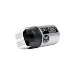
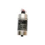
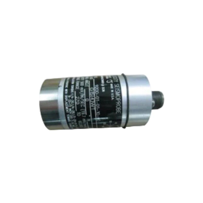
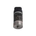
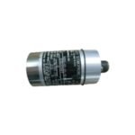
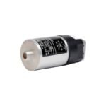
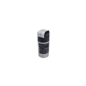
Configured for absolute casing vibration measurements in machinery monitoring networks, the Bently Nevada 9200-06-02-10-00 operates as a moving-coil velocity transducer. Specifically, the self-generating hardware functions without external power excitation and subsequently converts structural or bearing housing vibration velocity into a proportional analog voltage output. Consequently, this design executes the direct delivery of dynamic machinery velocity metrics to machinery protection monitors or diagnostic instruments.
Hardware Specifications
Parameter
Specification
Model
9200-06-02-10-00
Brand
Bently Nevada
Origin
USA
Weight
0.30 kg (10.5 oz) typical
Dimensions
41 mm diameter x 102 mm height
Operating Temp
-29 deg C to +121 deg C
Power Consumption
Self-generating (No external power required)
Sensitivity
20 mV/mm/s (500 mV/in/s) at 100 Hz, ±5%
Frequency Response
4.5 Hz to 1000 Hz (+0, -3 dB typical)
Mounting Orientation
0 deg to 180 deg universal mounting (Omnidirectional orientation)
Connector Configuration
Top mount connector interface (Inverted internal spring style layout)
Mounting Base Thread
M10 x 1.25 metric threaded stud
Transducer Dynamics and Operating Constraints
The Bently Nevada 9200-06-02-10-00 relies on internal moving-coil dynamics rather than eddy-current probe scaling to measure absolute structural velocities. Field setup replaces standard proximity probe gap voltage validation (-10 VDC targets) with mechanical alignment based on the calibrated mounting orientation code. Because this specific configuration utilizes the universal orientation spring package combined with a top-mount configuration, it can be physically deployed across omnidirectional angles from vertical to horizontal without requiring distinct mechanical calibration alterations. To preserve signal integrity across multi-transducer networks, the heavy anodized aluminum housing provides electromagnetic shielding; as a result, the hardware minimizes signal degradation when field lines route through parallel wireways.
Frequently Asked Questions
Q: What specific layout parameters do the options in the 9200-06-02-10-00 configuration define?
A: The option codes define a 0 to 180 deg universal/omni mounting orientation angle (06), a top-mount inverted style connector interface layout configuration (02), an M10 x 1.25 metric mounting base thread (10), and a configuration requiring no specialized agency approvals (00).
Q: Can this self-generating moving-coil transducer drive long field cable distances?
A: Yes. Because the transducer generates a low impedance voltage signal via its internal 1.25 kOhm nominal coil resistance, it can drive shielded instrumentation cables up to significant distances without high-frequency signal attenuation.
Field Installation Guidelines
Shielding and Grounding: First, secure the twisted-pair field wiring to the top-mount connector assembly. Afterward, ground the overall cable shield at a single point inside the instrument panel or monitor rack to prevent ground loop noise from corrupting the dynamic velocity wave signal.
Conduit and Routing Rules: Always route transducer output cables inside dedicated, grounded metal conduits. In addition, avoid running signal conductors parallel to high-voltage AC lines or variable frequency drive (VFD) motor cables to suppress electromagnetic noise.
Mechanical Mounting: Torquing forces affect sensor performance; therefore, tighten the M10 x 1.25 threaded mounting stud to exactly 5.6 N-m (50 in-lb) using a calibrated torque wrench. Ensure the mounting surface is clean, flat, and free of paint layers to allow proper transmission of high-frequency casing energy.
Additional information
Weight
0.30 kg
Dimensions
60 × 80 × 95 mm
0.0
Average Rating
Rated
(0 Reviews)
Rated
0%
Rated
0%
Rated
0%
Rated
0%
Rated
0%
Be the first to review “Bently Nevada 9200-06-02-10-00 Seismoprobe Velocity Transducer” Cancel reply














0.0 Average Rating Rated (0 Reviews)