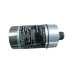
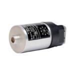
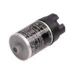
Obtain the original Bently Nevada 9200-03-05-10-00 horizontal moving-coil velocity seismoprobe transducer. We provide brand new, original stock parts with global shipping options for your immediate machinery protection needs.
Configured for absolute casing vibration measurement and structural integrity tracking in industrial rotating machinery, the Bently Nevada 9200-03-05-10-00 (9200 Seismoprobe Velocity Transducer) provides direct physical/electrical execution. Specifically, this self-generating electromechanical hardware utilizes a moving-coil matrix to convert mechanical case velocity directly into a proportional analog millivolt signal, enabling immediate downstream processing and machinery protection without requiring external excitation power.
Mounting Angle / Frequency Option: 90 deg +/- 2.5 deg (Horizontal), 4.5 Hz minimum operating frequency
-05
Connector Option: Terminal block top mount layout (No integrated cable)
-10
Mounting Base Option: Circular shape with M10X1 threaded stud configuration
-00
Agency Approval Option: Standard non-regulated execution, no hazardous area approvals
Hardware Specifications
Parameter
Specification
Model
9200-03-05-10-00
Brand
Bently Nevada
Origin
United States
Weight
300 g (10.5 oz) typical
Dimensions
41 mm Diameter x 102 mm Height
Operating Temp
-29 to 121 deg C
Power Consumption
0 W (Passive self-generating design)
Electrical Sensitivity
20 mV/mm/s (500 mV/in/s) +/- 5% at 100 Hz
Frequency Response
4.5 Hz to 1.0 kHz (+0 to -3 dB typical)
Internal Coil Resistance
1.25 kOhm +/- 5%
Transverse Sensitivity
Less than 10% maximum of the sensitive axis value
Rotor Dynamics and Transducer Conditioning
To achieve highly precise rotor dynamics analysis, this specialized horizontal sensor incorporates internal moving-coil mechanics that demand strict field alignment. Because the -03 option mandates a 90 deg physical orientation, the horizontal internal spring suspension requires accurate radial positioning to preserve the absolute linear velocity baseline. This mechanical tracking enables the monitor to isolate distinct 1X and 2X structural vibration components during machinery operation. Furthermore, the robust physical casing design ensures complete cross-talk suppression by eliminating magnetic field coupling between adjacent units. As a result, the internal hardware maintains sharp signal separation and clear analog waveform transmission even when technicians mount the transducer in high-density structural clusters alongside proximity probe networks tracking standard -10 VDC gap validation indices.
Frequently Asked Questions
Q: Does this specific velocity sensor require any external loop power or power from a 3500 rack?
A: No. The internal permanent magnet and moving-coil assembly function completely passively, converting physical mechanical momentum into an independent electromotive force (EMF) voltage output.
Q: What happens if an installer mounts this -03 configuration module in a vertical orientation?
A: Vertically mounting a 90 deg calibrated probe causes the internal coil suspension to rest hard against its mechanical travel limits. Consequently, this orientation error dampens horizontal tracking sensitivity and introduces extreme measurement distortion.
Q: How does the top-mounted terminal block affect field wiring replacement paths?
A: The -05 top mount terminal block features integrated screw terminals directly on the sensor cap. Therefore, technicians can replace worn field wiring or detach local conduits without discarding an otherwise functional transducer body.
Field Installation Guidelines
Mechanical Torque and Stud Engagement: Clean and machine the mounting surface completely flat and perpendicular to the chosen horizontal measurement plane. Ensure the M10X1 threaded stud engages at least 5 full threads into the bearing housing, and torque the sensor to exactly 5.6 N-m (50 in-lb) to prevent high-frequency mechanical resonance.
Shield Termination: Land the field wiring inside the top-mounted terminal block using crimped lugs. Run a twisted, shielded two-conductor cable to the monitor panel, and terminate the outer shield drain wire exclusively at the monitor chassis ground while keeping the field-side shield floating.
Conduit and Routing Separation: Enclose the transducer field wiring inside dedicated, grounded metallic conduits. In addition, route these low-voltage analog signal tracks completely away from conduits or trays housing high-voltage AC motor control circuits.
Additional information
Weight
0.3 kg
Dimensions
110 × 61 × 130 mm
0.0
Average Rating
Rated
(0 Reviews)
Rated
0%
Rated
0%
Rated
0%
Rated
0%
Rated
0%
Be the first to review “Bently Nevada 9200-03-05-10-00 Seismoprobe Velocity Transducer” Cancel reply


0.0 Average Rating Rated (0 Reviews)